Facebook
 Google
 GitHub
 Linkedin
Hi,
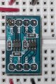
I recently purchased a 2-ch MDFLY voltage level translator which is a device that can up-shift or down-shift voltages depending how one configures it (see attached spec sheet).
Please could someone tell me why I get voltages on both transmit and receive pins with nothing connected. That is, I get 3.3V on the TXA and RXA pins and 5V on the RXB and TXB pins.
So when I feed in a 100Hz, 5V square wave on BNC-A (TXA) I see a very jaggedy 1.7Vpp square wave on BNC-B (RXB) and not a nice clean 3.3Vpp square wave as I was expecting. Why?
Am I missing something fundamental here in concept?
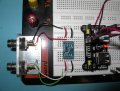
P.S. Another pic is attached showing the complete cct incl a 3.3V / 5V PSU. Not sure whether it will extract as I had to compress it as for some reason AAC would not accept a JPG. Only a PNG which my camera does not do. And please don't tell me to convert it to a PNG, 'cause I already tried that (on max compression) and the file size grew from 1.6MB to 8.5MB
;-)
Tnx
I recently purchased a 2-ch MDFLY voltage level translator which is a device that can up-shift or down-shift voltages depending how one configures it (see attached spec sheet).
Please could someone tell me why I get voltages on both transmit and receive pins with nothing connected. That is, I get 3.3V on the TXA and RXA pins and 5V on the RXB and TXB pins.
So when I feed in a 100Hz, 5V square wave on BNC-A (TXA) I see a very jaggedy 1.7Vpp square wave on BNC-B (RXB) and not a nice clean 3.3Vpp square wave as I was expecting. Why?
Am I missing something fundamental here in concept?
P.S. Another pic is attached showing the complete cct incl a 3.3V / 5V PSU. Not sure whether it will extract as I had to compress it as for some reason AAC would not accept a JPG. Only a PNG which my camera does not do. And please don't tell me to convert it to a PNG, 'cause I already tried that (on max compression) and the file size grew from 1.6MB to 8.5MB
;-)
Tnx
Attachments
-
22.2 KB Views: 39
-
1.6 MB Views: 23
Last edited: