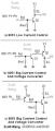
I know... but it's an internal logic signal to a more sophisticated controller (see post #1). In fact, I'm thinking that using a simple opto could be simpler. But I'd also have to use a transistor and a resistor to drive the opto. So maybe I'll just stick to this design, judging from its smaller size and component count.
And now that I'm using an N-FET instead of an NPN transistor, I no longer have to worry about how much current my MCU can source or sink.
Ahhhh... it's practically a totem-pole push-pull switch... As I mentioned before, I need to start thinking about those chips as more than just mosfet drivers. Very nice, thanks for the suggestion!
Thanks... I think I get the general principle now. One transistor is driving down the gate of the other one. Simple as that!
And in your circuit, the MCU is draining current through Q1's emitter and not sourcing any.
Thanks... I think I get the general principle now. One transistor is driving down the gate of the other one. Simple as that!
And in your circuit, the MCU is draining current through Q1's emitter and not sourcing any.
Correctimundo! Because the base of Q1 is connected to the +5V supply, the collector is pulled down towards 4.3V (= +5V - 0.7V), or is allowed to float up to the +12V supply rail allowing Q2 to turn off. You can adjust the current that the microprocessor is required to sink by adjusting the values of the three resistors.
 Facebook
 Google
 GitHub
 Linkedin