MC34063A 3.7v to 5.0V Step Up

Thread Starter

Utkarsh Verma

Joined Oct 30, 2016
102
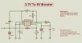
I'm planning on using the MC34063A in a step up circuit for my lithium ion batteries. What I aim to do is to step up the 3.7V to 5V. I'd like to get 0.5A current as well. While going through the datasheet, I found various formulae to calculate the values required for my circuit.
But the one thing I couldn't understand was the Fmin value. It is said in the datasheet that MC34063A can attain max frequency at 100kHz. What does it imply? Moreover, which value will be sufficient for my above explained circuit? Please tell me a clear value and the method of attaining or approximating the ideal frequency value.
I have attached the datasheet.
 

Attachments

Papabravo

Joined Feb 24, 2006
22,084
It implies that you can get to 100 kHz, but you may not want to. Most applications will use a frequency in the range 24 kHz to 42 kHz, with 33 kHz being a typical choice.
 

Thread Starter

Utkarsh Verma

Joined Oct 30, 2016
102
It implies that you can get to 100 kHz, but you may not want to. Most applications will use a frequency in the range 24 kHz to 42 kHz, with 33 kHz being a typical choice.
I think you didn't understand my question partly.
What I wanted to ask was what does frequency of this circuit mean? (by definition) And thanks for the value suggestion. Does it anyhow depend on the value being boosted?
 

Dodgydave

Joined Jun 22, 2012
11,395
the frequency can be set upto 100khz by the R/C values, this would depend on what current and output voltage you want to run at, some lower frequencies give better results.
 

DickCappels

Joined Aug 21, 2008
10,661
The frequency determines the maximum pulse frequency. It is a trade-off between component size (which usually relates to cost) and efficiency -switch too fast and you waste power. There is no direct relationship between frequency and the input and output voltages except as they relate to the component values.

Papabravo already mentioned some common frequencies in post #2 and he mentioned the typical choice;.
 

Thread Starter

Utkarsh Verma

Joined Oct 30, 2016
102
The frequency determines the maximum pulse frequency. It is a trade-off between component size (which usually relates to cost) and efficiency -switch too fast and you waste power. There is no direct relationship between frequency and the input and output voltages except as they relate to the component values.

Papabravo already mentioned some common frequencies in post #2 and he mentioned the typical choice;.
While using the calculator over here-http://www.nomad.ee/micros/mc34063a/
I came up with these values:
Vin-3.6V
Vout-5V
Iout-443mA
Vripple-10mV
Fmin-74kHz.

And I got these in return:
Ct=221 pF
Ipk=1499 mA
Rsc=0.2 Ohm
Lmin=10 uH
Co=2204 uF
R=180 Ohm
R1=1k R2=3k (5V)


Do you see any issue with these? Should I proceed with the circuit?
 

Attachments

DickCappels

Joined Aug 21, 2008
10,661
I did not check the calculations -figured the on-line calculator can do that. You should make R1 33 ohms because you are going to need 80 ma of base drive for the output transistor and you only have a 3.6 volt power supply from which to derive that.

One other thing for a future project is that you are driving the output to within 0.07% of its absolute maximum rating, which is pushing things a bit. Ok, pushing things a lot! If you were to make this power supply in any volume you would want to be more conservative. You might want to put this chip in a socket so it will be easy to replace when the time comes.


https://www.onsemi.com/pub/Collateral/MC34063A-D.PDF
 

Thread Starter

Utkarsh Verma

Joined Oct 30, 2016
102
I did not check the calculations -figured the on-line calculator can do that. You should make R1 33 ohms because you are going to need 80 ma of base drive for the output transistor and you only have a 3.6 volt power supply from which to derive that.

One other thing for a future project is that you are driving the output to within 0.07% of its absolute maximum rating, which is pushing things a bit. Ok, pushing things a lot! If you were to make this power supply in any volume you would want to be more conservative. You might want to put this chip in a socket so it will be easy to replace when the time comes.

Ok, I will use an IC base for the IC. So only R1 has to be corrected? The rest values are fine?
 

Papabravo

Joined Feb 24, 2006
22,084
I think you didn't understand my question partly.
What I wanted to ask was what does frequency of this circuit mean? (by definition) And thanks for the value suggestion. Does it anyhow depend on the value being boosted?
The reason the circuit is called a switching regulator is because it is built around an oscillator. The oscillator has two states. In one of the states power is transferred to the inductor, and during the other state the power from the inductor is transferred to the load. You can read more about a boost regulator here:

https://en.wikipedia.org/wiki/Boost_converter

What is always true, and something you must not forget, is that power out will always be less than power in. Sometimes it will be much less.
 

LesJones

Joined Jan 8, 2017
4,509
Powerbanks do what you want. They are a lithium cell with a stepup convrter to 5 volts. (They also contain a charging circuit which you would not need.) I have seen some of these in one of the £ shop chains. (I think poundworld or poundland.) It is not worth building a stepup converter when you can get one for a pound.

Les.
 
Top