MC34063 Boost with external NPN transistor

Thread Starter

araheem801

Joined Jan 25, 2017
1


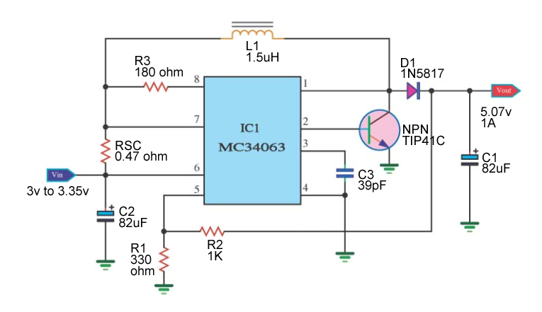
I need some help regarding the circuit I built (above). The way the circuit is built, it's supposed to output 1A @ 5v (with the peak current, Isw, being 5A). The inductor is 6.8A, the transistor (TIP41) is rated at 6A. The diode, D1, has a forward voltage of 0.475v, which is fine and has been calculated into the equation.

Anyway, my problem is this: the output voltage of the circuit measures the same as the input voltage when using the external transistor! When I reconfigure the circuit to run without the external transistor (ground IC pin 2), it outputs 5.07v (exactly how it should) but the output current can only go up to 0.3A (1.49A Isw, near the limit of the chip). So, what is the problem? Is it the transistor? Is it not turning on because the input voltage is 3v?

MC34063 Datasheet
TIP41C Datasheet
Ialso made this on bread board and 33pf cap and rsc is 1.5 ohm and rest of values are same but it is not woking at all plz halp me.
 

DickCappels

Joined Aug 21, 2008
10,187
Well, for starters, you might have killed something by trying to drive the TIP41 with a very high current. You need to put a current limiting resistor in series with pin 1 or pin 2 for the MC34063.
You also need to put some capacitors to ground, especially across the input. See the datasheet.
Now, what can you tell us about your circuit? Voltage measurements? Do you have a scope -what do you see?

1.5 uH? What frequency do you expect this to run at?
 

RichardO

Joined May 4, 2013
2,270
Well, for starters, you might have killed something by trying to drive the TIP41 with a very high current. You need to put a current limiting resistor in series with pin 1 or pin 2 for the MC34063.
You also need to put some capacitors to ground, especially across the input. See the datasheet.
Now, what can you tell us about your circuit? Voltage measurements? Do you have a scope -what do you see?

1.5 uH? What frequency do you expect this to run at?
DickCappels: Pin 1 is tied to the collector of the TIP41. I think that the 180 ohm resistor may limit the current into the base of the TIP41. What do you think?

A resistor should be added from the base of the TIP41 to ground to help the transistor turn off faster. I would use something like 100 ohms.

The graph in the data sheet shows that with a timing cap of about 100pf that the part will oscillate at about 120 KHz. I doubt that the part will work well with a 39pf timing cap. I wouldn't use less than 500 pf for the timing cap. The inductor value will have to be recalculated for the lower frequency. I will likely be a much large value. Also, make sure that the inductor you use has a saturation current of at least 2 amps --maybe more. The inductor resistance must be less than 50 mohms -- lower resistance is better.
 

DickCappels

Joined Aug 21, 2008
10,187
@RichardO
You're right, the 180 ohm resistor does limit the current into the base of the first transistor in the "tripple Darlington". The falling collector voltage on the TIP-41 will eventually provide feedback on the collector of the middle transistor thus limiting base current on the TIP-41. Had not thought through that before.

(edited)
 
Last edited:
Top