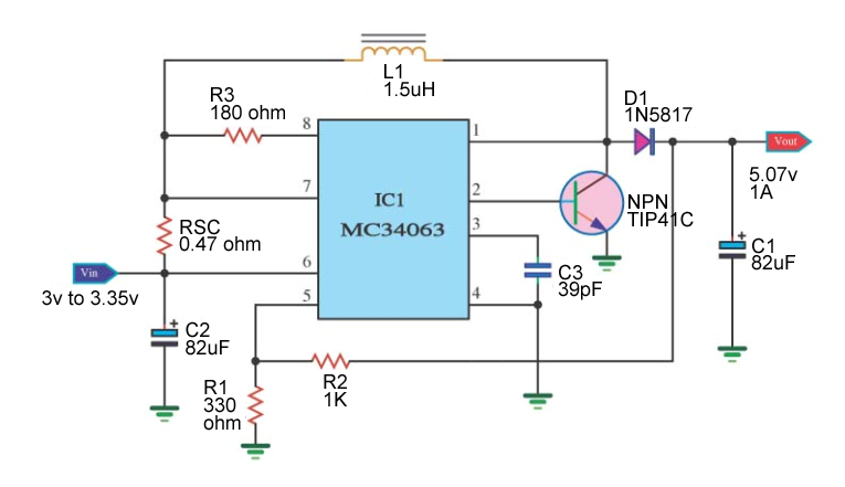
MC34063 Boost with external NPN transistor help

Thread Starter

letsbully

Joined Mar 23, 2012
34


I need some help regarding the circuit I built (above). The way the circuit is built, it's supposed to output 1A @ 5v (with the peak current, Isw, being 5A). The inductor is 6.8A, the transistor (TIP41) is rated at 6A. The diode, D1, has a forward voltage of 0.475v, which is fine and has been calculated into the equation.

Anyway, my problem is this: the output voltage of the circuit measures the same as the input voltage when using the external transistor! When I reconfigure the circuit to run without the external transistor (ground IC pin 2), it outputs 5.07v (exactly how it should) but the output current can only go up to 0.3A (1.49A Isw, near the limit of the chip). So, what is the problem? Is it the transistor? Is it not turning on because the input voltage is 3v?

MC34063 Datasheet
TIP41C Datasheet
 

crutschow

Joined Mar 14, 2008
34,464
The circuit look OK although you may want to add a low-value resistor from the transistor base to ground to minimize storage delay and improve the transistor turn-off speed.

Are you sure the transistor is wired correctly? Looking at the lead end with the tab down, the order is base, collector, emitter, left to right.
 

Thread Starter

letsbully

Joined Mar 23, 2012
34
How low of a value? 0.5 ohm? 2 ohm?


This is how I had my transistor wired. What's strange is that this is a brand new transistor that I just received. I tried a few transistors earlier with the same results, so I thought they were dead or something. The datasheet for TIP41 lists the emitter-base voltage as 5v. Does that have any impact on my circuit? I'm asking because my input voltage is around 3.5v and output voltage is only 5v <-*See Edit #1*

Also, I know breadboards are not the best for this kind of thing but the circuit works without the transistor installed (as of this moment outputting 4.x volts @ 0.25A, well within the configured range of 0.3A max) so I doubt that the breadboard would have that much of an impact on the transistor or something.

Edit #1: It's 5.07v without load and 4.3v under load. Could that be why? Although with the transistor Vout measures around the same voltage as Vin when measured without load too so that wouldn't make sense.
 
Last edited:

crutschow

Joined Mar 14, 2008
34,464
3V might be marginal to turn on all three transistors (three base-emitter drops in series is about 2.1V). Can you try a higher voltage to see if that helps?

The 0.47Ω value for Rsc gives a peak current limit through the inductor of about 0.6A since the current limit threshold is about 0.3V (see top right graph on page 9/23). I assume that's not what you want. For an Isw of 5A max. you would need Rsc to be about .06Ω
 

Thread Starter

letsbully

Joined Mar 23, 2012
34
I combined the two circuits I was working on by accident when I made the diagram in the first post (the one with the output of 0.3A and the one with the output of 1A) so the values are mixed up in the picture. I guess that's what happens when you're working on multiple things at once. The RSC was actually calculated to be 1.5ohm, not 0.47 ohm. The actual calculations are below. Oops.


But yea, I'll try using a higher voltage to see if that helps me figure this out. If that turns out to be the case, can I use a FET or something instead of the transistor to do the same thing the transistor is supposed to, but at a lower voltage? My input voltage HAS to be around 3v. Is there anything I can do?
 

crutschow

Joined Mar 14, 2008
34,464
MOSFETS typically require at least 3V to turn on so that won't help much. Can't off-hand think of any other configuration that would work better using that IC.

You have a related problem with that circuit anyway. The saturation (turn-on) voltage of the three transistors (two internal and one external) is about 2.1V. Thus your efficiency will be very poor with a 3V supply.

You might look if there's another IC that will work better for your requirements, such as one of these.
 

Thread Starter

letsbully

Joined Mar 23, 2012
34
Thanks a lot for your assistance thus far. I greatly appreciate it.

Ok, I did more testing. I connected a 5v source to the input with the external transistor present. The circuit ended up outputting 5.03v but the current that it output was the same as in the configuration without an external transistor which makes me think that something is going on where the transistor is either not activating or not working for some reason. The load connected to the circuit is normally rated to draw much more current and typically draws much more than 300mA if allowed to. All of the connections were tested and appeared functional, no breaks in continuity, etc.
 

crutschow

Joined Mar 14, 2008
34,464
Thanks a lot for your assistance thus far. I greatly appreciate it.

Ok, I did more testing. I connected a 5v source to the input with the external transistor present. The circuit ended up outputting 5.03v but the current that it output was the same as in the configuration without an external transistor which makes me think that something is going on where the transistor is either not activating or not working for some reason. The load connected to the circuit is normally rated to draw much more current and typically draws much more than 300mA if allowed to. All of the connections were tested and appeared functional, no breaks in continuity, etc.
Did you reduce the value of RSC? I explained how that is limiting your current in my previous post.
 

Thread Starter

letsbully

Joined Mar 23, 2012
34
I missed that part of your post. Thank you for reminding me of it. I think that my 6A inductor might be broken. How likely is it that it's defective from the factory? Or could it be that its inductance, being 1.5uF, is too low to work with 3v? (although that probably doesn't make sense if the 22uH inductor works just fine).

I forgot that I had my 2A inductor on the breadboard when I reduced the RSC and connected the transistor. It worked with a Vin of 2.8v! The output was 0.65A (the voltage dropped from 5.2v to around 4v or so under load which is acceptable). Then I realized my mistake and put in the 6A inductor. The Vout was 2.8v again so I've concluded that there is something wrong with the inductor, because it was the only part I swapped and the circuit "broke".

The output of 0.65A is too much for the inductor because the peak current is over 3A, correct? I'm still trying to figure out how that works. If the peak switching current is going to be 5A, then the inductor has to be rated for 5A right? Or does the inductor have to be rated for what I want my output current to be?

Thank you very much for your assistance over the coarse of this thread. It has been more than helpful and a great learning experience.

I have another question because I've been trying to understand the role of this component since I began working with this circuit. What is the role of the "small" (rated in pF) capacitor on pin 3? It seems to not affect the circuit much (just by looking at the output anyway) when I change its value. Do you happen to have a simple explaination?
 
Last edited:

crutschow

Joined Mar 14, 2008
34,464
The cap on pin 3 determines the oscillator frequency. It affects the transistor switching losses and what the ripple current in the inductor is.

Also how did you go from 22μH to a value 1.5μH for your inductor?

The inductor does need to be rated for the peak current.

The values your design calculator came up with are not correct. This one appears to give better results.
 

Thread Starter

letsbully

Joined Mar 23, 2012
34
That all makes much more sense to me now!

I had values determined for 2 different circuits based on the calculator tool I used. The first circuit would not use an external transistor and therefore would only output around 300mA. That circuit used a 22uH inductor. The second circuit would use an external transistor and would output 1A. This circuit would have a 1.5uH inductor because all the other component values were scaled down, based on the calculator.

Thanks for the link. That site gives a correct RSC value. I wonder why the tool I used to calculate all the values does not give a correct RSC. The tool is called "MC34063 Step Up". Using that calculator, if you change the value of the "small" capacitor from let's say 100pF to 10pF, the size of the inductor goes from say, 100uH to 15uH. That's how I got 1.5uH. But thinking back now to what you just said, if that capacitor sets the frequency and 220pF is about 100kHz, then going lower should increase the frequency and the chip can't go above 100kHz, so the 1.5uH inductor would not work. Right?

I just downloaded another calculator tool from sourceforge. How do these values look? Do they look good? I'm particularly talking about the Rd resistor in the image. It was 180ohm before using other calculators and in my current circuit, but now this new calculator sets it at 22ohm. Would that work? That's pretty much the only thing I'm still not too clear on in this circuit. We've talked about all the other components.


One thing that concerns me is the Vsat value. This calculator for the image above had it at 0.7v. The previous calculator that I used to calculate the values in the beginning of this thread had it set at 1.3v. Which is correct for MC34063A?

Edit: Here are the values from the calculator for the image above:

 
Last edited:

takao21203

Joined Apr 28, 2012
3,702
most switcher ICs work with almost any standard power inductor.
Only for max. efficiency you need well matched values.

The new technology (Mhz range) is a different class, using smaller inductors.

This IC = typically 100uH or some 100uH.

The value you calculated is ridiciously low (for this chip), and if you ask me, too low, means wrong!


Install 100uH inductor as a starting point. Amperage is not relevant for testing.
If in doubt, show the inductors you have here on the forum.

You could try using the chip output to short the base current for the external transistor, supplied by a resistor from Vcc.

If I use transistors correctly, or install them into my tester, the C/E voltage is close to 0V, not 0.7V, that is a wrong value.

Also simulation software might be of use to you, LTSpice etc.
To test various way of driving transistors at this voltage (3V).

So what I suggest is actually called "external saturated switch" in the manual. Maybe also can be used for NPN.
 

crutschow

Joined Mar 14, 2008
34,464
...................

Thanks for the link. That site gives a correct RSC value. I wonder why the tool I used to calculate all the values does not give a correct RSC. The tool is called "MC34063 Step Up". Using that calculator, if you change the value of the "small" capacitor from let's say 100pF to 10pF, the size of the inductor goes from say, 100uH to 15uH. That's how I got 1.5uH. But thinking back now to what you just said, if that capacitor sets the frequency and 220pF is about 100kHz, then going lower should increase the frequency and the chip can't go above 100kHz, so the 1.5uH inductor would not work. Right?

I just downloaded another calculator tool from sourceforge. How do these values look? Do they look good? I'm particularly talking about the Rd resistor in the image. It was 180ohm before using other calculators and in my current circuit, but now this new calculator sets it at 22ohm. Would that work? That's pretty much the only thing I'm still not too clear on in this circuit. We've talked about all the other components.

One thing that concerns me is the Vsat value. This calculator for the image above had it at 0.7v. The previous calculator that I used to calculate the values in the beginning of this thread had it set at 1.3v. Which is correct for MC34063A?
Those values look OK for a 300mA maximum output current. Note that the value for L is a minimum value. You can always go larger.

Rd is a relatively non-critical value which determines the amount of drive current to the output transistor. Looks like they are using a forced β of about 10 for the output transistor (rather than the data sheet value of 20) to reduce its saturation voltage somewhat.

The MC34063A has a 0.7V maximum saturation voltage. It will be about 1.3V with the added external transistor.

For that chip you need to operate at a maximum of 100kHz or a minimum Ct of 220pF.
 

Thread Starter

letsbully

Joined Mar 23, 2012
34
Awesome.

Now one final thing, for the voltage divider sensing, does it make much of a difference if the R1 and R2 values are 3.3K and 10K, 330ohm and 1K, 33ohm and 100ohm, 3.3ohm and 10ohm? Which is better? According to the other calculator I used, it said that a lower value is better for higher switching frequencies. How low is low? Is 3.3ohm and 10ohm too low? Is 330ohm and 1K too low?
 

crutschow

Joined Mar 14, 2008
34,464
Awesome.

Now one final thing, for the voltage divider sensing, does it make much of a difference if the R1 and R2 values are 3.3K and 10K, 330ohm and 1K, 33ohm and 100ohm, 3.3ohm and 10ohm? Which is better? According to the other calculator I used, it said that a lower value is better for higher switching frequencies. How low is low? Is 3.3ohm and 10ohm too low? Is 330ohm and 1K too low?
Too low and you waste power in resistor dissipation. For example the 10ohm and 3.3ohm values would draw 376mA and dissipate about 1.9W with a 5V output.

Too high and the input bias current can cause errors in the regulated voltage.

Typically you want to keep the values somewhere between 1kΩ and 100kΩ.
 

Thread Starter

letsbully

Joined Mar 23, 2012
34
Awesome. You've been very helpful. My circuit is working exactly as intended now. The output is 0.32A (the mathematically calculated output is 0.358A) on the breadboard. Thanks a lot! I hope that in the future this thread is helpful to someone who had the same questions I did.
 

Thread Starter

letsbully

Joined Mar 23, 2012
34
I actually did forget to ask one other thing. How can I run this circuit in parallel without just connecting the outputs together. What I mean is, can some of the components be shared between the ICs?
 

crutschow

Joined Mar 14, 2008
34,464
I actually did forget to ask one other thing. How can I run this circuit in parallel without just connecting the outputs together. What I mean is, can some of the components be shared between the ICs?
I don't see anything that can be shared.

And you should not parallel the outputs. Because of tolerance differences in the output voltage the one with the highest output will hog the current.
 

oymyakon

Joined Jun 25, 2012
1
Hi guys,
I have built a small project using the Mc34063 as above and the problem i have is the current limiting. It all works fine as you load up the power output i am using it for step down from 36 to 24v. But if you short it out with an ammeter the current goes to over double the current limit value. Am i missing something?
 
Top