Facebook
 Google
 GitHub
 Linkedin
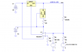
Hola Ron,Agustín, here is another way to do this. The LM317 regulator is inside the op amp's feedback loop, and basically acts as a bullet-proof voltage follower within the loop.
You don't have to consider the 1.25v vref when calculating Vout/Vin
I spent almost one day relearning how to import models and subcircuits into LTSpice. I was totally at lost but thanks to a post from Eric and one from you, I solved that. Now, back to the original subject.
After simulating your variation and my circuit I am not sure what is the actual advantage of yours, because I want an output from -0.25V to -30V.
The only way I found is applying a (+1V) offset after amplifying the control signal as in my attached circuit.
Comments appreciated.
Attachments
-
3.9 KB Views: 9