MC33072 - Am I exceeding something?

Thread Starter

atferrari

Joined Jan 6, 2004
5,011
Today I tested the attached circuit which basically works as expected but after maybe one minute, the opamp becomes rather warm if not hot to touch.

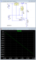
Am I asking too much from it? The current, as shown is 11 mA (steady) through the whole range.By reading the datasheet I could not conclude if I am exceeding anything. Honestly, I do not know where to look at for this.

With the scope I can see noise everywhere, of up to 50 mV pk-pk. The whole PCB appears plagued by that noise.

Any comment, appreciated.

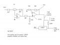
Had to use Paint for drawing instead of Corel. Sorry if it looks horrible :eek:
 

Attachments

GopherT

Joined Nov 23, 2012
8,009
You have 37 volts of supply voltage (check data sheet if that is ok)

Also, your output from op amp to the lm337, you have 150 ohm to the negative supply rail and nothing to the adj. you need some more resistance on your output (less current output) or you will burn up the op amp (you are will on your way ). Good luck.
 

#12

Joined Nov 30, 2010
18,224
Took me a minute, but he's right. Maybe try dumping the idle current of the 337 with a jfet to the +5 rail. A 2N4857A would work or you can build one from a bipolar transistor and a few diodes and resistors.
 

Thread Starter

atferrari

Joined Jan 6, 2004
5,011
Took me a minute, but he's right. Maybe try dumping the idle current of the 337 with a jfet to the +5 rail. A 2N4857A would work or you can build one from a bipolar transistor and a few diodes and resistors.
Could you suggest something? I am afraid that I would loose the possibility
of controlling Vout as I am actually doing now (albeit with a too warm op amp...:mad: )
 

Thread Starter

atferrari

Joined Jan 6, 2004
5,011
Took me a minute, but he's right. Maybe try dumping the idle current of the 337 with a jfet to the +5 rail. A 2N4857A would work or you can build one from a bipolar transistor and a few diodes and resistors.
Something like this, I think. (Still prefer Corel!!)

Diodes and resistors? Where? What for?
 

Attachments

#12

Joined Nov 30, 2010
18,224
What you have done is move the heat to a transistor. My idea moves the heat to a transistor, just in a different way. After you dump the minimum current of the regulator chip, the control pin needs about 100 microamps. The wasted current is not part of the control circuit. My circuit seperates them, yours just moves the heat.
 

Attachments

Last edited:

Ron H

Joined Apr 14, 2005
7,063
What you have done is move the heat to a transistor. My idea moves the heat to a transistor, just in a different way. After you dump the minimum current of the regulator chip, the control pin needs about 100 microamps. The wasted current is not part of the control circuit. My circuit seperates them, yours just moves the heat.
I don't see any advantage to your circuit has over his. His doesn't require a pot to set the current.

@Agustín:
Where does the 1V reference come from?
 

#12

Joined Nov 30, 2010
18,224
Dumping the minimum idle current seperately reduces the load on the opamp to 100 ua. You can choose for your self whether that is an advantage. There are also ways to do it without a potentiometer, but you already know that.

Personally, I'd just reach into my drawer of 2N4416 jfets and select one for the right load or plug in 2 of them if I didn't have one in the high current range. No resistors at all in that case.
 
Last edited:

#12

Joined Nov 30, 2010
18,224
I guess I'd have to get lucky and find one that is better than the guaranteed voltage or use one of many other constant current circuits.
 

Ron H

Joined Apr 14, 2005
7,063
I guess I'd have to get lucky and find one that is better than the guaranteed voltage or use one of many other constant current circuits.
Power is also an issue. You will have to find one with a higher power rating, or use multiple devices in parallel.
Any current sink or emitter follower you use is going to have to dissipate 10mA*35V=350mW. Any TO-92 package is going to get hot enough to burn your finger at that power level.
I might use another LM337. See attachment.
 

Attachments

Thread Starter

atferrari

Joined Jan 6, 2004
5,011
What you have done is move the heat to a transistor. My idea moves the heat to a transistor, just in a different way. After you dump the minimum current of the regulator chip, the control pin needs about 100 microamps. The wasted current is not part of the control circuit. My circuit seperates them, yours just moves the heat.
I tested my idea with a 2N1711 (VceR = 50V - Ptot =0.8 W) inside the loop.

It works with the TO93 case hot to touch through the upper half of the range. The opamp stays barely warm now.

No matter what I would use to take the 10 mA load for the LM337, I should expect the same. Power has to be disipated, right?
 

Ron H

Joined Apr 14, 2005
7,063
I tested my idea with a 2N1711 (VceR = 50V - Ptot =0.8 W) inside the loop.

It works with the TO93 case hot to touch through the upper half of the range. The opamp stays barely warm now.

No matter what I would use to take the 10 mA load for the LM337, I should expect the same. Power has to be disipated, right?
That's right. You could use a medium power NPN as the emitter follower.
I suggested the LM317 because the package can handle more power than a TO92, and it's a part you are already using.
 

Thread Starter

atferrari

Joined Jan 6, 2004
5,011
That's right. You could use a medium power NPN as the emitter follower.
I suggested the LM317 because the package can handle more power than a TO92, and it's a part you are already using.

Yes, I noticed your post. As soon as can have few minutes at the bench I will test it. Thanks.
 

Ron H

Joined Apr 14, 2005
7,063
Agustín, here is another way to do this. The LM317 regulator is inside the op amp's feedback loop, and basically acts as a bullet-proof voltage follower within the loop.
You don't have to consider the 1.25v vref when calculating Vout/Vin.

EDIT: Attaching LM337.zip.
 

Attachments

Last edited:

Thread Starter

atferrari

Joined Jan 6, 2004
5,011
Hola Ron, I am a little bit at lost with your last cricuit. Not taking into account the 1.25 V? How comes...?

Could you post the .asc file so I can get the subcircuit for the LM337 and then see how it works?

Gracias.
 
Last edited:

Ron H

Joined Apr 14, 2005
7,063
Hola Ron, I am a little bit at lost with your last cricuit. Not taking into account the 1.25 V? How comes...?

Could you post the .asc file so I can get the subcircuit for the LM337 and then see how it works?

Gracias.
I had the current source in my previous post upside down.:(
I will change the schematic in the previous post to correct this error, and include the .asc file there also.
 

Thread Starter

atferrari

Joined Jan 6, 2004
5,011
I had the current source in my previous post upside down.:(
I will change the schematic in the previous post to correct this error, and include the .asc file there also.
Yes. The last thing I did last night was to check the recommended circuit in the LM337 datasheet. Negative currents as in this, confuses me.

Thanks for posting the whole thing.
 
Top