MC2100 Motor Controller solid led problem

Thread Starter

hozone

Joined Dec 26, 2012
36
Hi all,
I'm again working on my MC2100 board.
I've yet repair this board here: https://forum.allaboutcircuits.com/...-low-voltage-transformer.199676/#post-1898686
That problem was related to SMPS.
Now I've another kind of problem on this board.
Sometimes, is happens after 5 min of usage, but it may happens after 20 too. The motor stop spinning. I've made investigations.
When the motor stop spinning I've
LED: solid red
HD2 PWM seems ok: I can see PWM, so I think main controlling board is working
HD2 9V DC output seems ok: is 8.9V almost, it is stable when it works and when it stop working.
HD5 5V output is ok when is working and when it's not

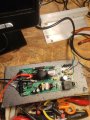
Now I've moved the board to my bench.
I'm supplying the board with mains (under fuse), and injecting 20Hz PWM 5V DC pk-pk.
Just those two connected. First test shows the led blinking fast.
Am I right testing it this way?
The only thing it seems to me led is blinking faster on bench than on the treadmill.
Have you got any idea of what it can be?

Odd problem like this are not simple to solve :(
 

Attachments

MaxHeadRoom

Joined Jul 18, 2013
30,557
Normally it is a slow steady blink when motor is running.
The other codes are a faster blink followed by a pause, different numbers of pulses between a pause indicates the area of problem.
 

Thread Starter

hozone

Joined Dec 26, 2012
36
Thank you.
By the way on bench is working.
Is 20hz ok for tests?
Find attached how fast is the bench blinking, does it seems ok?

Maybe it's something related to load, I mean on the treadmill after a while it stops working, the led stays on. On overload conditions it should blink at slower speed if I understand, so before stopping it should blink at that speed, or no?
 

Attachments

MaxHeadRoom

Joined Jul 18, 2013
30,557
That looks like the correct rate of flash, and 20hz PWM is also the right signal.
Check it with a incandescent lamp in place of the motor,
 

Thread Starter

hozone

Joined Dec 26, 2012
36
Thanks! It's 130VDC you are right :)
Problem is that I have 220V incandescent here in Italy, I can try with that on bench but I'm not sure.

Find attached the led speed when attached to the treadmill main PWM generator.
In this picture it was attached just the cables below:
1) mains cables L/N/Earth
2) motor cables + and -
3) GND,9V,PWM from HD2

I'll search for something 90..150V DC around in my house, but I think I've nothing of that voltage.
If I don't find nothing, I'll try powering the PWM board with an extenal 9V supply, and then use just the GND and PWM cable of the HD2 connector, leaving all the other connectors (except the motor and mains) free.
Another way could be to build/buy a PWM generator and use it as external board. Trying to use just the PWM to check what's wrong.

If you have any other suggestion I'm open to it.
 

Attachments

MaxHeadRoom

Joined Jul 18, 2013
30,557
I use the board stand-alone on the bench for testing, using a 20hz PWM generated signal.
The flash rate appears the same as the one I have working on the bench now.
 

Thread Starter

hozone

Joined Dec 26, 2012
36
I've not been able to reproduce the issue on bench. So I've put it on treadmill again.
Summer is almost ended so I'm gonna start using the treadmill soon.
Now it works, but I suppose it will stop working after a few.
I've connected the view board (the one that generate the PWM) with just 3 cables. GND +9V and the PWM.
9V seems fine, it's 8.95 and if I remember it's fine even when the treadmill stop working.
But there is something strange.
When I measure the PWM, if the PWM cable is connected to the board i measure 20Hz with Vppk 1.3V, if it's disconnected it's a 3V3 PWM signal.
I suppose the 3V3 signal is ok, right?
The 2V drop sounds a little bit strange to me. Or is it the way it is supposed to work?
 

MaxHeadRoom

Joined Jul 18, 2013
30,557
Do you have a resistor in series with your HD2 P4, the PWM signal in?
The reason is, that the opto input resistor is very low, especially if you are using 9v signal! :(
 

Thread Starter

hozone

Joined Dec 26, 2012
36
Thanks.
I've take a look at the schematic. I'm thinking about monitoring the PWM pin at the microcontroller side. Looking at what happens there when thing goes wrong and led doesn't blink.
I see there are a few Pulse With Modulation Set Point Pin, 2 on sheet 6 and 1 on sheet 2. Maybe better to take out the board and investigate it with multimeter set to continuity.
What do you think? It may worth? I mean maybe it's the optocoupler failing and PWM does not pass it through after a while?
 

MaxHeadRoom

Joined Jul 18, 2013
30,557
It is better to trouble shoot on the bench. But important to use the right series resistor in the opto circuit.
Input current 50ma max.
 
Last edited:

Thread Starter

hozone

Joined Dec 26, 2012
36
Found nothing on the bench, so I decided to mount it back. Last time I've also replaced the second low voltage electrolytic, so both the switching output caps are now new.
It works for three weeks almost. This morning stop working. Then if I give it a STOP and START it goes for 1 min. I suppose that if I leave it unplugged for a couple of hour it will works some minutes more.
Anyway, I leave it at 2Km/h starter, and removed the HD5 plug, so the feedback speed. It keeps working again.
HD5 is coming from the back of the motor, so I suppose it's some kind of hall sensor with a wheel to detect the movement. Maybe some dust on it and it stops working?
Have this ever happens to you?
I've to investigate further on this.

Thanks
 

Thread Starter

hozone

Joined Dec 26, 2012
36
Yes, without feedback, just the HD2 connected to a PWM generator. Than I mounted all back to treadmill, it works for 3 weeks almost, today stop working. I leave it START at 2Km/h, to investigate it on the board. As soon as I've removed the HD5 it starts spinning again. That is why I think it's something related to feedback.
 

gaber2611

Joined Mar 14, 2013
321
The board don't have some soldering lose In some component or area?
Don't have any lose of tracks?
Do you have something which show a big photo of the board to look?, like microscope etc?
 
Top