Facebook
 Google
 GitHub
 Linkedin
Hi E,hi,
Looks promising, the Slave to Master should also be ok.
E
Update:
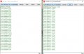
As you may have noticed, at start up msg1 from M to S is 1234 and the S to M is ABCD
As they receive that msg, they swap over and send back what they received and so on,
I removed the last post smiley, as I thought the PICs were exchanging, but now find it was MASTER's two different MSG1s.
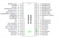
Just going to add the missing SLAVE to MASTER SS wire.
C

") (Smiley back in)
(Smiley back in)