MASTER and SLAVE PICs using SPI in Oshonsoft

Thread Starter

camerart

Joined Feb 25, 2013
3,724
hi C,
Looking at all the additional inputs to these PIC's and the way they are all cross connected in that edited drawing, shows IMHO it is too complex a project for you to develop/complete using the Oshonsoft IDE

I would recommend that you review the project specification and its purpose.

Eric
Hi E,
So far I've been mainly working on the TRANSMITTER, and all of the modules are working apart from the SLAVE HW SPI sending DEGREES.

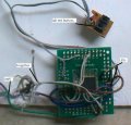
Following a similar comment from you a few posts ago, I have now built another PCB with a 4xway MUX switch. Using 3x INPUTS to the MASTER UART (RADIO, COMPASS and DEGREES), I can test that before going any farther.
C.
 

ericgibbs

Joined Jan 29, 2010
18,766
hi C,
Draw a block diagram of the TX and the RX modules, showing all the peripherals as blocks.
Also the actual data formats ie: ASCII, HEX etc In and Out of each of the data blocks.
Also the protocol on how the data blocks are being exchanged between the modules.
Also the required timing of the data transfers, between the modules.

You need a working diagram as explained above, so that you fully understand what you need for Hardware and the programs for each PIC.

E
 

Thread Starter

camerart

Joined Feb 25, 2013
3,724
hi C,
Draw a block diagram of the TX and the RX modules, showing all the peripherals as blocks.
Also the actual data formats ie: ASCII, HEX etc In and Out of each of the data blocks.
Also the protocol on how the data blocks are being exchanged between the modules.
Also the required timing of the data transfers, between the modules.

You need a working diagram as explained above, so that you fully understand what you need for Hardware and the programs for each PIC.

E
Hi E,
Am I correct that you want a tidied up version of the image in my #299 post, but with each of the named peripherals (Compass. GPS etc) in a box, with better description of how they interact with each PIC?

NOTE: I've just seen your comment in #281, which answers one of my previous questions.
 

ericgibbs

Joined Jan 29, 2010
18,766
Morning C,
It's not me that needs a complete, tidied version of the block diagram of your project.
You need it in order to check that the idea's you have in mind are feasible.

Consider that you have already run out of program memory and had to change to PIC's with a about the maximum available program memory for that range of PIC's.
You have had to make changes also because of insufficient RAM memory.

Remember the Oshonsoft Basic compiler/IDE is not yet able to support many of the newer PIC types, so you have a pending problem with the IDE.

So sketch out a block diagram of the final/complete project and use that to check and highlight the problem areas.

E
 

Thread Starter

camerart

Joined Feb 25, 2013
3,724
Morning C,
It's not me that needs a complete, tidied version of the block diagram of your project.
You need it in order to check that the idea's you have in mind are feasible.

Consider that you have already run out of program memory and had to change to PIC's with a about the maximum available program memory for that range of PIC's.
You have had to make changes also because of insufficient RAM memory.

Remember the Oshonsoft Basic compiler/IDE is not yet able to support many of the newer PIC types, so you have a pending problem with the IDE.

So sketch out a block diagram of the final/complete project and use that to check and highlight the problem areas.

E
Hi E,
I see!
Any sensible electronics engineer, would do just that, and know what they want, then design the PCB and programs to suit. I'm afraid, I can't do that because to me this is a naive organic adventure. I've had the change PICs and redesign the PCBs quite a few times, because of theses reasons. It's not been easy for me, or the forum members here and elseware, but it's been interesting for me, and I hope others too.
At the moment I've not much idea how to add the control section of the program, and simply hope I don't run out of memory. ( I mean PIC memory not mine! Mine went a long time ago;))

Anyway, if you post your SPI programs, I can see if I can include them, or finish the extra UART PCB, and see if that works.

Cheers, C.
 

ericgibbs

Joined Jan 29, 2010
18,766
hi C,
I am not being difficult with you , quite the contrary, I am trying to advise you that the way you are tackling this project will give you nothing but grief.:(

If I post my Hardware SPI proving programs written in Oshonsoft basic, they will not be usable in your project as they stand.
The difficulty you will encounter is when you come to plumb them into your main programs, which you still have not debugged with respect to the control and timing required.

When you consider the number of input peripherals you already have linked to the PIC.s and the fact you are driving Servo's shows that the synchronisation and timing problems are the details which need to be addressed first.

This is why I keep beating the 'you need a complete block diagram which shows the sync and timing required' drum..

Eric
 

Thread Starter

camerart

Joined Feb 25, 2013
3,724
hi C,
I am not being difficult with you , quite the contrary, I am trying to advise you that the way you are tackling this project will give you nothing but grief.:(

If I post my Hardware SPI proving programs written in Oshonsoft basic, they will not be usable in your project as they stand.
The difficulty you will encounter is when you come to plumb them into your main programs, which you still have not debugged with respect to the control and timing required.

When you consider the number of input peripherals you already have linked to the PIC.s and the fact you are driving Servo's shows that the synchronisation and timing problems are the details which need to be addressed first.

This is why I keep beating the 'you need a complete block diagram which shows the sync and timing required' drum..

Eric
Hi E,
Ok, thanks. I appreciate your warnings.

Sadly, being low skilled, and 'red lineing' the brain box, I'll plod on in the best way I can till I run out of road, then perhaps take up something less taxing instead :)
C.
 

ericgibbs

Joined Jan 29, 2010
18,766
hi,
Why don't we deal with the topic of you thread.?
Do you have a test rig you could set up,using two 18F4620's [ I know that you use that type].

If you can do that I will post what I have working in Ohonsoft basic for the Master and Slave.

In that way you can explore just what can and cannot be done using hardware SPI for communication between the PIC's

This will give you a base reference working system on which you can try your analyser/programs and improve your understanding of SPI

E
 

Thread Starter

camerart

Joined Feb 25, 2013
3,724
hi,
Why don't we deal with the topic of you thread.?
Do you have a test rig you could set up,using two 18F4620's [ I know that you use that type].

If you can do that I will post what I have working in Ohonsoft basic for the Master and Slave.

In that way you can explore just what can and cannot be done using hardware SPI for communication between the PIC's

This will give you a base reference working system on which you can try your analyser/programs and improve your understanding of SPI

E
Hi E,
As you may recall I've converted to Surface mount, so any testing needs a PCB designing and etching. I have boards with 18F4620 MASTER and 18F4431 as SLAVE, will your programs work with these? The 18F4431 is used as it has the required QEI PINS.
C..
 

ericgibbs

Joined Jan 29, 2010
18,766
hi C,
I explored using the 18F2431, [which I had on the bench] the lower Flash memory version of the 18F4431.
Using a HW SPI connection between a 18F4620 and a 18F2431, running internal 8MHz clock.

Initially could not get any SPI output from the 18F2431, all the other LED tests were OK.

Finally tracked it down to an error in the Oshonsoft IDE Configuration set bits, it Configures Reg 3H as 0x80 [ that sets the /MCLR pin]
however that same register should set the Bits for a 18F2431 as 0x9d , which multiplexes PORTC with SPI, and not PORTD as per the 18F4431.

Currently running SPI tests, which look promising intend sending Vlad a bug report.

So when programming the 18F4431 ensure that the CONFIG REGs are set correctly.

E
 

Thread Starter

camerart

Joined Feb 25, 2013
3,724
hi C,
I explored using the 18F2431, [which I had on the bench] the lower Flash memory version of the 18F4431.
Using a HW SPI connection between a 18F4620 and a 18F2431, running internal 8MHz clock.

Initially could not get any SPI output from the 18F2431, all the other LED tests were OK.

Finally tracked it down to an error in the Oshonsoft IDE Configuration set bits, it Configures Reg 3H as 0x80 [ that sets the /MCLR pin]
however that same register should set the Bits for a 18F2431 as 0x9d , which multiplexes PORTC with SPI, and not PORTD as per the 18F4431.

Currently running SPI tests, which look promising intend sending Vlad a bug report.

So when programming the 18F4431 ensure that the CONFIG REGs are set correctly.

E
Hi E,
Great stuff!
I can send you an 18F4431 surface mounted on a TEST PCB. Here's one, I used for testing. (I can remove my 'beautiful' wiring if you like, or make a fresh one)

NOTE: This should go through the 5MM postal system this time:)
C.
 

Attachments

ericgibbs

Joined Jan 29, 2010
18,766
hi C,
I would prefer not to start using SMT PIC's when debugging/developing a project, I use DIP devices on a bread board.
When the project is proven, only then do I create a PCB and use a mix of SMT and DIL. devices.

Looking at your posts over the 'years', I would say that you have spent hours making PCB's which you have either scrapped or had to modify.
Also how do you know the final size and optimum layout of the PCB/s until until you have a working prototype.??

I would rather stick to a system of project development that's successfully worked for me in a commercial environment.

E
 

Thread Starter

camerart

Joined Feb 25, 2013
3,724
hi C,
I would prefer not to start using SMT PIC's when debugging/developing a project, I use DIP devices on a bread board.
When the project is proven, only then do I create a PCB and use a mix of SMT and DIL. devices.

Looking at your posts over the 'years', I would say that you have spent hours making PCB's which you have either scrapped or had to modify.
Also how do you know the final size and optimum layout of the PCB/s until until you have a working prototype.??

I would rather stick to a system of project development that's successfully worked for me in a commercial environment.

E
Hi E,
Yes, it's taken me years of messing about to get to beginners level. That's the trouble with having a scatter brain o_O
C.
 

jpanhalt

Joined Jan 18, 2008
11,087
Re: Prototypes

Awhile back I went to solderable breadboards. Sparkfun, Adafruit, eBay, and others have them. The ones I use are laid out much like the familiar solderless breadboards, so the changeover is quite easy. I use the solderless versions now only for the simplest, temporary circuits. When troubleshooting a program or programming problem (e.g., device not recognized error), you can't beat the reliability of a soldered connection for piece of mind.

Here's a link to an Adafruit version: https://www.adafruit.com/product/571

I use 24 awg Kynar insulated solid wire. Looks nice, is not too small, and the insulation doesn't burn back.
 

Thread Starter

camerart

Joined Feb 25, 2013
3,724
Re: Prototypes

Awhile back I went to solderable breadboards. Sparkfun, Adafruit, eBay, and others have them. The ones I use are laid out much like the familiar solderless breadboards, so the changeover is quite easy. I use the solderless versions now only for the simplest, temporary circuits. When troubleshooting a program or programming problem (e.g., device not recognized error), you can't beat the reliability of a soldered connection for piece of mind.

Here's a link to an Adafruit version: https://www.adafruit.com/product/571

I use 24 awg Kynar insulated solid wire. Looks nice, is not too small, and the insulation doesn't burn back.
Hi J,
Previously I used a professional breadboard, with it's own transformer, LEDs and switches, but once I changed to Surface mount, I had to use the type I attached in #311. apart from anything else, it helps me learn to solder S/M.
C.
 

jpanhalt

Joined Jan 18, 2008
11,087
The 0.1"/2.54 mm spacing allows some SMT devices (e.g., 1206 size) to be soldered easily between holes, should you be so inclined. I almost always use TH components with them, though, or adapter boards for IC's with good female contacts.

Here's a recent example:

upload_2019-8-10_8-11-36.png

The board with push button switches is a utility board with hardware debouncing that I use. Saves having to write debounce routines.
 

Thread Starter

camerart

Joined Feb 25, 2013
3,724
The 0.1"/2.54 mm spacing allows some SMT devices (e.g., 1206 size) to be soldered easily between holes, should you be so inclined. I almost always use TH components with them, though, or adapter boards for IC's with good female contacts.

Here's a recent example:

View attachment 183596

The board with push button switches is a utility board with hardware debouncing that I use. Saves having to write debounce routines.
Hi J,
Once I looked at modern chips, I found that surface mount is necessary and I used a very small one for the Compass, here's the PCB.
For the 18F4431 also using the adopted S/M it would need a different board to the one you show. Here's diagram to show the sizes.
C.
 

Attachments

ericgibbs

Joined Jan 29, 2010
18,766
hi C,
These two program communicate and exchange data via HW SPI, Internal clock 8MHz. Master 18F4620 ,, Slave 18F2431
Msg1 = 1234<crlf> & Msg2 ERIC<crlf> repeating at 1 sec rate.

Rem: ref the CONFIG 3H setting to suit your App & 18F4431

Done my bit, its all yours!..:rolleyes:

E
 

Attachments

Thread Starter

camerart

Joined Feb 25, 2013
3,724
hi C,
These two program communicate and exchange data via HW SPI, Internal clock 8MHz. Master 18F4620 ,, Slave 18F2431
Msg1 = 1234<crlf> & Msg2 ERIC<crlf> repeating at 1 sec rate.

Rem: ref the CONFIG 3H setting to suit your App & 18F4431

Done my bit, its all yours!..:rolleyes:

E
Hi E,
Thanks, they look interesting.
Both of the programs don't compile. See attached.
I'm using IDE version 3.62.
C.
 

Attachments

Top