MASTER and SLAVE PICs using SPI in Oshonsoft

Thread Starter

camerart

Joined Feb 25, 2013
3,842
hi,
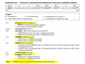
Just change the 'cr' to some other label, you are using a later version of Oshonsoft than the one I use.
E
Hi E,
The 18FX431 PICs don't like [ ALL DIGITAL ] I think that [ SSPCON.SSPEN = 1 'Configure SCK,SD0,SDI,/SS ] satisfies it.

With [ CR ] changed to [ CRTN ] and [ ALL DIGITAL ] commented out, it compiles. Is this ok?
C
 

ericgibbs

Joined Jan 29, 2010
21,462
hi,
Just try it and post the results, monitor the serial testing UART data outputs.
E

BTW: the variable 'cr' is 0x0d which is a carriage return code.
 

Thread Starter

camerart

Joined Feb 25, 2013
3,842
hi,
Which pins are you using for HW SPI, ref this image.?
E
Hi E,
All of the green ones, and RC6 for program, and I switched over for UART testing. ( I commented that this was problematic), but I didn't know that RC3 could be used for UART. At the moment there is no connection at RC3.
C
 

ericgibbs

Joined Jan 29, 2010
21,462
hi,
RC3 is a SW UART just for testing the SPI... Serout PORTC.3, 9600, "Slave Ready", CrLf 'software uart

As you are using PORTC for SPI, I would set CONFIG3H as 0x9d for the initial test.
 

Thread Starter

camerart

Joined Feb 25, 2013
3,842
Hi E,
Just set:
---------------------------------------------------------------------------------
Define CONFIG1L = 0x00
Define CONFIG1H = 0x08 'INT OSC
Define CONFIG2L = 0x0e
Define CONFIG2H = 0x20
Define CONFIG3L = 0x1c
Define CONFIG3H = 0x02 '0x9f 'Change to suit the 18F4431 as required
Define CONFIG4L = 0x80
Define CONFIG4H = 0x00
Define CONFIG5L = 0x0f
Define CONFIG5H = 0xc0
Define CONFIG6L = 0x0f
Define CONFIG6H = 0xe0
Define CONFIG7L = 0x0f
Define CONFIG7H = 0x40
------------------------------------------------------------------------------------
Will add a wire to RC3 for the UART

C.
 

ericgibbs

Joined Jan 29, 2010
21,462
hi,
The original 0x02 looks incorrect!, where did that come from.?
I will also check the 18F4431 Configuration in OSH
E

EDIT:
Compiled a 18F4431 file, image shows the 2431 and 4431
 

Attachments

Last edited:

Thread Starter

camerart

Joined Feb 25, 2013
3,842
hi,
The original 0x02 looks incorrect!, where did that come from.?
I will also check the 18F4431 Configuration in OSH
E

EDIT:
Compiled a 18F4431 file, image shows the 2431 and 4431
Hi E,
My 4620 has a Crystal perhaps that's where 0x02 came from. It's set to 0x08 now.
C.
 

Thread Starter

camerart

Joined Feb 25, 2013
3,842
The details I posted are not for the 18F4620, its the the 18F4431.
Both PICs use internal 8MHz for the test programs.
Morning E,
I know, but as usual, it will take me ten goes before I get it as you say.
4431 RC3 wire added.
Just starting tests.
I may have to stop soon today, as I'm going to a Hamfest.
C
 

Thread Starter

camerart

Joined Feb 25, 2013
3,842
Hi E, TRANSMITTER
18F4620 MASTER:

Initially it ran slow, so I changed the CONFIG to '8MHz' XTL, and now it's ok.

I added START UP LEDS
Is this section ok?
______________________________________________________
Dim dta As String
Dim Crtn As String
Crtn = Chr(0x0d) 'carriage ret

Dim x As Byte
Dim y As Byte

Symbol rled = LATC.1 'ADDED
Symbol yled = LATC.2 'ADDED
'START UP LEDS
rled = 1
WaitMs 1000
rled = 0
yled = 1
WaitMs 1000
yled = 0

msg1 = "1234" + Cr + Lf
msg2 = "ERIC" + Cr + Lf
____________________________________________________________
C
 

Attachments

ericgibbs

Joined Jan 29, 2010
21,462
hi,
In my version of the IDE the 'cr' was not defined as a RESERVED, so I created cr= 0x0d
In your later IDE version 'cr' is a RESERVED word, same as the LF in both our versions.

So the msg's in you post are OK.... you should be able to REM out the
Dim Crtn As String
Crtn = Chr(0x0d) 'carriage ret

If it is running correctly you should see the msgs on the Serial outputs, ???

E
 

Thread Starter

camerart

Joined Feb 25, 2013
3,842
hi,
In my version of the IDE the 'cr' was not defined as a RESERVED, so I created cr= 0x0d
In your later IDE version 'cr' is a RESERVED word, same as the LF in both our versions.

So the msg's in you post are OK.... you should be able to REM out the
Dim Crtn As String
Crtn = Chr(0x0d) 'carriage ret

If it is running correctly you should see the msgs on the Serial outputs, ???

E
Hi E,
My [ CR ] question was regarding: where I changed the [ CR ] to [ CRTN ] in the MSG1 it shows [ +CR + LR ] is this correct, as if you look in the image at # 332 it shows it not Carriage returning. Also there is no [ DIM LF as STRING ] is this ok?

Now over to SLAVE 4431.
C
 

Thread Starter

camerart

Joined Feb 25, 2013
3,842
hi C,
The idea was to supply you with a test program, why do you keep adding to it BEFORE you have it working.????
E
Hi E,
Looking at the image in #324, the tracks on my PCB are using PORTD, so I had to add the TRIS for it. Is this not correct?
C.
 

ericgibbs

Joined Jan 29, 2010
21,462
hi,
Looks promising, the Slave to Master should also be ok.
E

Update:
As you may have noticed, at start up msg1 from M to S is 1234 and the S to M is ABCD

As they receive that msg, they swap over and send back what they received and so on,
 
Last edited:
Top