The UART pins cannot be remapped in PIC18F4431. There is no Peripheral Pin Select (pin mapping) option in that PIC. it is better if you output the Slave's CAP2BUFL data on say PORTD Leds. There is no point of printing Slave's SSPBUF value on Slave's UART or PORTx.
The UART pins cannot be remapped in PIC18F4431. There is no Peripheral Pin Select (pin mapping) option in that PIC. it is better if you output the Slave's CAP2BUFL data on say PORTD Leds. There is no point of printing Slave's SSPBUF value on Slave's UART or PORTx.
The UART pins cannot be remapped in PIC18F4431. There is no Peripheral Pin Select (pin mapping) option in that PIC. it is better if you output the Slave's CAP2BUFL data on say PORTD Leds. There is no point of printing Slave's SSPBUF value on Slave's UART or PORTx.
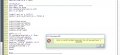
Proc initialize_uart(baudrate As Word)
Hseropen 9600 'baudrate<<<<<<<<<<<<<<<<<<<<<<<<<<<<<<<<<<<<<<<<<<<<<<<<<
Hserout "PORTB ", #PORTB, CrLf '<<<<<<<<<<<<<<<<<<<<<<<<<<<<<<<<<
WaitMs 100
End Proc
_____________________________________________________________________
(') = commented out so not in the program.
If you want to print CAP2BUFL or PORTB data on UART then you have to try this.
Hi J2,
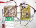
The purpose of the thread is to get the two PICs to 'talk' via SPI, but only for testing, I have added a UART.
C.
I know and that is what my code does. I didn't post the master code in my previous post because it was already posted a few posts back and it has not changed.
The Slave code in my previous post prints CAP2BUFL value on PORTB and UART and also send it to Master through hardware SPI.
 Facebook
 Google
 GitHub
 Linkedin