Marble Accelerator For Game Room

Thread Starter

12VOptimusPrime

Joined Feb 17, 2026
4
I saw this project that takes metal marbles and accelerates them through a magnetic coil online and wanted to ask a few questions before I start working on the project. The goal is the create a track around the game room where the ball travels around the sides of the walls and hits these electromagnet stations where the ball is given a boost of velocity to make it to the next check point and continue traveling around the room. Maybe later I can incorporate lights at the checkpoints and such but for now I want to keep it simple.

The project I am referring to can be found here: https://www.instructables.com/Electromagnetic-Marble-Accelerator-for-Gravitrax/

The principle: ball travels past a mark, a signal is sent to a controller which is then relayed to turn on a coil which powers the marble just long enough to get to the center of the coil and then shut off the magnetic field. This prevents the magnetic field from pulling back on the marble after the midway point.

My question is, can this circuit be created with an IR beam to detect the ball, sub-second 12V adjustable timer relay (similar to an NE555), MOSFET rated for the coil current, flyback diode, and the coil itself? I dont mind programming the ESP32 or Arduino, but for others who might want to make one I was thinking the adjustable timer relay might be easier. What are your thoughts on the hardware to build something like this? Or do you have other ideas on how to make this circuit more simple using a pre designed board/module.
 

wayneh

Joined Sep 9, 2010
18,136
So you basically want to recreate that circuit without the Arduino? I believe that is definitely doable. At worst you lose a hair of efficiency but it seems to me that a micro-processor is overkill for this.

This forum has a rule against discussing rail-guns and I'm asking a moderator to take a look at this. I think you're OK but we should get their thumbs up before digging in.
 

Thread Starter

12VOptimusPrime

Joined Feb 17, 2026
4
So you basically want to recreate that circuit without the Arduino? I believe that is definitely doable. At worst you lose a hair of efficiency but it seems to me that a micro-processor is overkill for this.

This forum has a rule against discussing rail-guns and I'm asking a moderator to take a look at this. I think you're OK but we should get their thumbs up before digging in.
I can definitely understand because I have seen some where they use large voltage and it sounds very dangerous. This one is a small project for the game room and I only plan to use 12V to power the a 100g coil. Thank you for asking for me!
 
Many moons ago (ok, decades), I made something like this, except it accelerated something more cylindrical than spherical. The "track" was a piece of narrow hard plastic tubing, with a series of coils made from basic solid core wire. All had one end commonly wired, the other end of each coil went to a series of thumbtacks in a line, and was all powered by a small 12 volt AGM.

Placing the cylindrical metal object at one end, simply "striking/rubbing" the bare wire from the common side (with the battery in between in series) along the series of thumbtacks, I could accelerate the object fast enough for it to strike a soda can placed a few feet away (no damage was done to the can).

I had always intended to revisit the project, but never did. I figured that all I needed to do to make it "automatic":

1. Between each coil, and immediately prior to the first, put an IR LED and photo-transistor pair across the tube. You might also be able to use a photo-reflector pair.
2. Wire the photo-transistor to another transistor or mosfet that would trigger the coil.
3. The object would pass thru, and the blocking of the photo-transistor would trigger the coil directly in front of the object.

This would attract the object into the coil, and by the time it passed, the coil would be turned off, so that the object could pass unimpeded. That's all that should've been needed. No microcontroller, no delay relays or anything like that.

Additional things to make it better (more efficient) would be to wind much better coils (I figured using pre-wound solenoid coils would work best), and also adding large capacity "buffer" caps for voltage dumping (back then, I was thinking large electrolytics; today, I might opt for super-capacitors).
 

Danko

Joined Nov 22, 2017
2,231

MisterBill2

Joined Jan 23, 2018
28,116
Consider that a 7/16 steel ball rolling around a game room big enough for one person to stand up in will not be very impressive, nor even very easy to see, I suggest thinking the whole project over very carefully.
AND consider that the 7/16 ball is similar in size to a .38 caliber slug, it may have the potential to be unsafe.
 

MisterBill2

Joined Jan 23, 2018
28,116
REally, if the ball is rolling on a conductive track for that segment, it could easily close a circuit to enable the electromagnet. The second benefit is zero standby power consumption, aside from being simple and inexpensive.
 

MisterBill2

Joined Jan 23, 2018
28,116
Unfortunately, if the ballis rolling on a track with two wires forming the trigger switch, agreat deal of accuracy is required in crreating the arrangement. Consider also a 700 volt power supply, probably a tripler from the 220 volt mains, with a capability of at least one amp, will be a serious open shock hazard. While the overall concept is quite interesting, the effort to make it either safe or functional will be quite a bit.
 
if the ball is rolling on a conductive track for that segment, it could easily close a circuit to enable the electromagnet. The second benefit is zero standby power consumption, aside from being simple and inexpensive.
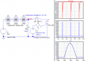
Before reading the entire post I had the same idea. In fact, I stopped reading and drew this picture:
Screenshot 2026-08-31 at 8.41.34 AM.png
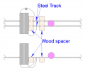
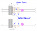
The idea here is to have some power source that might be just strong enough to move the ball to a higher location and let gravity roll the steel ball down to the next boost station (trap).

Unfortunately, if the ballis rolling on a track with two wires forming the trigger switch, agreat deal of accuracy is required in creating the arrangement.
The idea here is that you can adjust the location and the length of the two steel contactors to achieve optimal launching of the ball with the most efficiency.

Consider also a 700 volt power supply, probably a tripler from the 220 volt mains, with a capability of at least one amp, will be a serious open shock hazard.
I didn't get the impression the TS wanted this ball to be traveling around the room at break-neck speeds. Bill commented on the size of the ball and given the scale of the track - traveling around the game room - that's going to be a fairly unimpressive display, so I agree with Bill on that. Use of a larger ball would improve the visibility of the system. But it would also require a higher power source to be able to accelerate the ball from trap to trap.
 
Last edited:
Screenshot 2026-08-31 at 8.41.34 AM.png
The two views are (one) from the top looking down (upper diagram). The lower view is looking from the side. The two tracks are held separate from one another by a wooden support. I'm sure your track is going to have some sort of support system. I used wood as an example; you can use whatever you can to insulate the two steel tracks from the rest of the track. Or maybe the entire track is wooden, then all you need is two sections of steel track to act as the switch. The length should be long enough to turn the magnet on before the ball arrives inside the trap (coil) but shut down before the ball wants to exit the trap.

Once you have that part figured out you can adjust the location of the trap to optimize the system. No need for optical sensors or Hall effect sensors. Just a simple "Coil ON" - "Coil OFF" circuit. Battery powered or powered from a power supply.

As for the voltage required - a whole lot depends on the size of the coil and the amount of energy you want to impart to the steel ball. Also needed in the calculations is the weight of the steel ball and how much power it will take to accelerate it to an appropriate speed to reach the next trap. After all that you're going to need to figure out how many traps you're going to need. Suppose you need a dozen traps: if you go with sensors or µC processors then it starts to run the cost up quickly. Simpler is better. Less expense and more ease of construction. Start by testing coil sizes and ball sizes. How much voltage it takes to move the ball to the next trap.
The idea here is to have some power source that might be just strong enough to move the ball to a higher location and let gravity roll the steel ball down to the next boost station.
I don't think it would take a lot of power to push the ball up a few inches and let gravity take the ball to the next trap.
 
It appears the producer of this video used some sort of sensor when the steel ball gets close enough to the trap and briefly fires it to the next trap. It also appears the builder used some sort of low voltage. For this small loop the TS used six coils, each with its own sensor.
 

MisterBill2

Joined Jan 23, 2018
28,116
That yoo-toob display looked a bit-off, like a whole lot of yoo-toob stuff, as I see it. I did not see anything that looked like a sensor in that video.
It could be a string of pulses from an external source.
 

B-JoJo-S

Joined Jan 3, 2026
493
That yoo-toob display looked a bit-off, like a whole lot of yoo-toob stuff, as I see it. I did not see anything that looked like a sensor in that video.
OK, I accept your POV. I think I see some sort of PCB on the side of each coil, as many coils as can be seen. The rest are assumed to have a sensor board to control each individual coil.

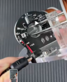
Better still, here's a screen grab from that video at about 7 seconds:
Screenshot 2026-08-31 at 3.29.09 PM.png
You can see an IR transmitter and receiver on either side of the track inlet. Can't tell what all the other components are but it's obvious there are control boards on each coil.
 
Top