Make: Electronics through discovery Exp.#11 Fluctuations

Thread Starter

Klara88

Joined Dec 19, 2017
14
Hi All
I am trying to replicate a circuit from the textbook mentioned above and I do not get the expected results. Can you help me?
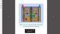
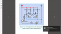
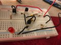
Please see below the intended circuit and my circuit. Any suggestions?
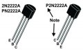
I have spend over 2 hrs in 2 days trying to find what's wrong but I cannot see it. I checked the bands on the resistors and all connections several times.If I remove the connection from the e(emitter) of the pn2222 on the RHS to the -(negative) of the LED I get steady light.
This is not HW just practice.
 

Attachments

Thread Starter

Klara88

Joined Dec 19, 2017
14
Look at the markings on the transistors very carefully. There are two styles of pinouts. Make sure you have the right one.

View attachment 142539
I have PN2222 and upon online checking it is the same as 2N2222. I checked the pins online I should have set them in the right direction. I flipped them around once before posting would that have ruined them?
 

GopherT

Joined Nov 23, 2012
8,009
I have PN2222 and upon online checking it is the same as 2N2222. I checked the pins online I should have set them in the right direction. I flipped them around once before posting would that have ruined them?
Unlikely to ruin them.

If you checked polarity of capacitors and it still doesn't work note that Sometimes when the resistors are so mangled like yours, the legs are not strong enough to push into the spring-loaded holes. Pull each out, straighten them and then re-insert and be sure you get a good feel that they are in.

If that doesn't help, the spring loading may be defective on one of your holes. Try rebuilding it in a new area of the board (or use a different board.

Also, there are some defective Red LEDs out there with reverse polarity (inserted into the molding machine backwards). Make sure your LED lights up. Test it with a resistor and 9v battery (see lessons earlier in the book). It is possible that your LEd is just backwards.
 

Thread Starter

Klara88

Joined Dec 19, 2017
14
Those little bead capacitors are certainly tanalium. Look for a small (+) near one leg.
I looked there's no other writing on the capacitor but 335 on one side. I tried flipping them around in the circuit as well but it does not work. Should my capacitors be polarized for this experiment?
 

dl324

Joined Mar 30, 2015
18,326
I flipped them around once before posting would that have ruined them?
If you reverse biased the base-emitter junctions enough to break them down, beta will be reduced (significantly).

The junctions will still test as good, but you won't have the expected current gain. The beta test function on a DMM might show it. A curve tracer will give a definitive answer.
 

Thread Starter

Klara88

Joined Dec 19, 2017
14
Unlikely to ruin them.

If you checked polarity of capacitors and it still doesn't work note that Sometimes when the resistors are so mangled like yours, the legs are not strong enough to push into the spring-loaded holes. Pull each out, straighten them and then re-insert and be sure you get a good feel that they are in.

If that doesn't help, the spring loading may be defective on one of your holes. Try rebuilding it in a new area of the board (or use a different board.

Also, there are some defective Red LEDs out there with reverse polarity (inserted into the molding machine backwards). Make sure your LED lights up. Test it with a resistor and 9v battery (see lessons earlier in the book). It is possible that your LEd is just backwards.
Gopher
I tried all you said. My Led is ok. I checked and rechecked all contacts. I rebuilt in another board. Thank you for helping.
 
@Klara88 You are very close and I hope you don't give up now.

You may have fried a PN2222, but you can test all three of them using the parts that you already have.

tester.jpg
If you can set up a circuit like that above on your breadboard.... when you connect Vin to + the LED should light. When you connect Vin to - the LED should not light. You already have the 1K (R) and 4.7K (Rb) resistors, so you can test each PN2222 and see if any have been fried.

Divide and conquer.
 

dl324

Joined Mar 30, 2015
18,326
Once it was constantly off and another time constantly on. Now its off.
You can use a circuit like this to test your transistors:
upload_2017-12-27_12-28-40.png
If the transistor is backwards, there won't be enough reverse bias on the BE junction to kill beta. If the transistor doesn't turn the LED on in either direction (assuming center terminal is the base), it's bad.
 

bushrat

Joined Nov 29, 2014
209
I build something similar, and I noticed that they don't always autostart. Sometimes it needs a little push to start oscillating. What i do is is disconnect either positive or negative wire and reconnect. after few tries, its oscillating.
 

Thread Starter

Klara88

Joined Dec 19, 2017
14
@Klara88 You are very close and I hope you don't give up now.

You may have fried a PN2222, but you can test all three of them using the parts that you already have.

View attachment 142574
If you can set up a circuit like that above on your breadboard.... when you connect Vin to + the LED should light. When you connect Vin to - the LED should not light. You already have the 1K (R) and 4.7K (Rb) resistors, so you can test each PN2222 and see if any have been fried.

Divide and conquer.
DQ I love your idea but I'm confused I have Vcc, Vin and 0V. Which one connects to the +, which one to - and do I ground the 0V?
 
DQ I love your idea but I'm confused I have Vcc, Vin and 0V. Which one connects to the +, which one to - and do I ground the 0V?
0v goes to ground (-) on the breadboard. Vcc goes to (+) on the breadboard. Take a wire from Vin to (+) to light the LED and then move it to (-) and it should not light - that is Vin to + and then Vin to -.

BTW what is your (+) 9V?
 

Thread Starter

Klara88

Joined Dec 19, 2017
14
Did you get it working?

The circuit schematic shows two 470kΩ resistors (yellow-purple-yellow-gold) from +V to the base of each transistor.

I see 470Ω (yellow-purple-brown-gold) in the photo that you posted.
You did it! YES I just did I had 470 instead of the 470K on, wow it works! You can tell I just started working with breadboard circuits:)
 
Top