Make an Old PC PSU Your Bench Variable Power Supply

Thread Starter

hazim

Joined Jan 3, 2008
435
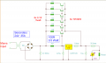
Power through a resistor is P = I^2 * R, so a 0.47 ohm resistor with 1A flowing through it dissipates 0.47W and has a voltage of V = IR or 0.47V across it. Choose a resistor at least double the rating. 2W is adequate for high reliability.
That's what I said. Then the 22 Ohm in the circuit is wrong? But I saw similar circuit with R=100Ω 0.5W ! I doubt with myself. :confused:

Edit:
Here is the same:
http://users.belgacom.net/hamradio/schemas/6-20amps_regulatable_powersupplies_on6mu.htm
R9 is 47 Ohm 0.5 watt

I think I found it, they are using the regulator to change the voltage only, and even 30mA passes through the power transistors and not the regulator.

0.7V/22Ω = 0.03A.
0.03^2 x 22 = 0.02W only. 0.5W resistor is sufficient, even 1/8W resistor is sufficient!! Now I think I'm right :D
 

Attachments

Last edited:

tom66

Joined May 9, 2009
2,595
That's what I said. Then the 22 Ohm in the circuit is wrong? But I saw similar circuit with R=100Ω 0.5W ! I doubt with myself. :confused:

Edit:
Here is the same:
http://users.belgacom.net/hamradio/schemas/6-20amps_regulatable_powersupplies_on6mu.htm
R9 is 47 Ohm 0.5 watt

I think I found it, they are using the regulator to change the voltage only, and even 30mA passes through the power transistors and not the regulator.

0.7V/22Ω = 0.03A.
0.03^2 x 22 = 0.02W only. 0.5W resistor is sufficient, even 1/8W resistor is sufficient!! Now I think I'm right :D
Just use a 0.5W resistor. The regulator should pass a maximum of 1A. 1A and 100 ohms is I^2 / R or 0.1W, more than you predict, so choose a 1/4W or 1/2W resistor. Also, I'm not sure what the 1A fuse on the regulator's output is for. Remove it, if it blows it will cause the output voltage to shoot up. The regulator has adequate internal protection against short circuits and overcurrent.

Also, the circuit posted is for 30A. Just so you know, at 24V secondary and 30A, that is 720W, which is a lot!!! Make sure you have a VERY big and probably quite expensive 1KVA transformer if you plan to do 30A. Also, the transistors dissipate an average of 360W, so active cooling will be required.
 

Thread Starter

hazim

Joined Jan 3, 2008
435
I didn't said that I'll build those circuits I posted in my previous post. I just used them as examples. What is I^2 / R or 0.1W? If the current should pass 1A and it is 100 ohm then RI^2 = 100W and a 200W resistor should be used. Anyway I may have misunderstand you, and in my previous post I mentioned everything that explains the problem and the solution. So everything is ok and I'll continue my work.

Regards,
Hazim
 

tom66

Joined May 9, 2009
2,595
I didn't said that I'll build those circuits I posted in my previous post. I just used them as examples. What is I^2 / R or 0.1W? If the current should pass 1A and it is 100 ohm then RI^2 = 100W and a 200W resistor should be used. Anyway I may have misunderstand you, and in my previous post I mentioned everything that explains the problem and the solution. So everything is ok and I'll continue my work.

Regards,
Hazim
Yeah, you're right, I got it wrong (was tired.) In theory, P = I^2 * R. But passing 1A will drop 100V across it by V = IR, this is impossible, so you will not get anywhere near 100W. Experiment with a 5W resistor, as that is probably the absolute maximum needed.
 

Thread Starter

hazim

Joined Jan 3, 2008
435
In post#21 (in the top of this page) I write my explanation for this issue. These circuits are using the regulator to regulate the voltage only. They don't pass 1.5A or 1a or even 0.1A. in the circuit I'm building the 22 ohm resistor limits the current of the regulator to around 30mA I think... If a load draws 100mA then the current will pass from the power transistors. In post#21 I clarified this idea.
 

tom66

Joined May 9, 2009
2,595
In post#21 (in the top of this page) I write my explanation for this issue. These circuits are using the regulator to regulate the voltage only. They don't pass 1.5A or 1a or even 0.1A. in the circuit I'm building the 22 ohm resistor limits the current of the regulator to around 30mA I think... If a load draws 100mA then the current will pass from the power transistors. In post#21 I clarified this idea.
Yes, that was the point I was trying to make - the regulator will pass an absolute maximum of 1A or so through it because higher currents would cause it to shut off; in reality, it would probably only draw a few mA quiescent current.
 

Thread Starter

hazim

Joined Jan 3, 2008
435
I'm back :)

I faced hard time in the previous weeks that forced me to not post and participate in this forum.

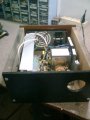
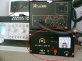
I have finished the project and it's really nice especially with the extras that I've added.

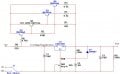
Here is the circuit:


The switch J1 is actually a two line switch. When switching to -12V, R9 is disconnected and a 470Ω resistor is connected across the output terminals. Both resistors are 2W resistors.

Resistors R3 and R4 are 5W resistors, I used 10W but 5W resistors will work (max. power is 5A*5A*0.1=2.5W, doubling is 5W.)

Q2 is a medium power NPN transistor (its current and power rating should be between 2N2905 and 2N3055...), actually I forgot what was the transistor I used, but I found a suitable one around here. I used a small heatsink for it.

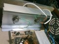
I used a huge heatsink for Q3 and Q4. U1 doesn't need and heatsink since the circuit is designed such that even less than 100mA current will be drawn from the power transistors. The voltage regulator U1 is used for voltage regulation only.

The 12V line of the PSU can supply current up to 10A. The -12V can supply only about 1A, so I connected a switch between -12V and 0V to switch between 1.2-12V 10A supply and 1.2-24V 1A supply. The fan is connected to the same switch to run on 12V when using the selecting 12V 10A and on 5V when selecting 24V 1A.

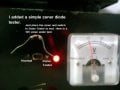
The zener tester is very simple, it tests zener diode voltages to about 20V. When the zener tester switch is switched, the needle is switched to measure the voltage across the zener diode where the zener is placed in series with a 2kΩ resistor between the 12V and -12V lines.

A 10A fuse is used at the output of the unit, even though the PCU has an overload/short-circuit automatic shutdown feature.


Attachments

Thread Starter

hazim

Joined Jan 3, 2008
435
Sorry there is a mistake in the circuit, the collectors of Q2, Q3, Q4 and emitter of Q1 are connected to +12V line.

Regards,
Hazim
 
Top