Mains voltage frequency measurement

Thread Starter

sparkyjf

Joined Feb 13, 2020
13
Hi all

I am in the process of building a mains power monitoring box and although I had a nice digital "all-in-one" meter, I wanted to add some analogue metering just because I personally like how this looks.

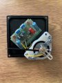
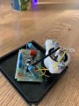
Right or wrong, I purchased a 72mm x 72mm 220V rated class 1.5 45-55Hz frequency meter off of Ali Express (part URL available on request - photo attached for reference). This arrived today and being of the cautious type I thought I would connect it up to my variac to see how it behaved.

Lo and behold, the meter starts reading straight away with the variac set at its minimum, and the pointer moves up roughly linearly as I increase the AC voltage, reaching FSD at about 18V. A 50Hz reading is achieved at around 12V AC.

I have never used this type of meter before, but I note that whilst in the UK they are available from suppliers such as RS and Farnell, they start at £30 and go up from there - my meter cost US$7 from Ali Express. All the datasheets for the UK spec ones show that they can just be connected straight across the mains supply, but it's pretty clear if I do this with my meter then I'll fry it.

So my question is - is this meter a "fake" (e.g. an AC voltmeter which someone has stuck a 45-55Hz scale to), or is there a special way you should drive such meters that I'm completely missing.

Thanks in advance for your help

James

IMG_2024.jpg
 

MaxHeadRoom

Joined Jul 18, 2013
28,617
I suspect it is a simple case of the internal electrics/electronics require a minimum voltage to operate!
Especially if it reached 50Hz at 12v!
Max.
 

ebeowulf17

Joined Aug 12, 2014
3,307
Are you sure that it was ever meant to find the frequency for you? There are TONS of gauges and meters out there that read in whatever units and scale you want, but are just responding to a range of voltages or currents as the control source.

I mean, the fuel gauge on your car is a fairly dumb dial that responds to pre conditioned electrical signals generated elsewhere in your car. It doesn't have a little tube full of gas running all the way to your gas tank! Analog panel meters that read in dB SPL don't generally have a built in mic and preamp - they also respond to a signal generated in some other set of electronics.

I suspect that this thing might just be a simple indicator, and that you need to build a frequency to voltage conversion circuit to drive it. Pure speculation on my part though. I'm making a fairly wild guess and freely admit that I may be wrong.

Have you tried testing it with a variable DC source? It would be interesting to see what it does and doesn't respond to, although of course you'd want to be careful not to fry it!

If you could share pics of the connection points, link to where you bought it, etc. things might become more clear.
 
Weird, it says 220VAC on the faceplate. I would not expect it to read at merely 18VAC. But there is a 36VAC version, as well as the usual 100V, 127V, 220V, 380V versions for this SQ-72 frequency meter.

I would take it apart, the needle already looks scuffed. Just don't HIT/WRECK the pointer when you pull off the front faceplate. It has electronics inside which would tell us what's going on.
Also you could try drive it with a signal generator, most will make 25Vpp and see if it responds to frequency verses amplitude. It might be an AC voltmeter or something with a fake faceplate, so just a resistor and rectifiers inside.
 

Thread Starter

sparkyjf

Joined Feb 13, 2020
13
Thank you everyone for your replies - in answer to the questions I've been asked, here's some more details:

- DC supply - it doesn't like a DC input at all - with the inputs one way round, the meter goes the wrong way, but if I reverse the polarity the pointer never rises. I suspect this is due to the rectifier inside and polarity of the diodes, but more in a minute.
- Signal generator - I set my signal generator to 12V output, sine wave, 50Hz (which incidentally makes the pointer read 50Hz). I tried changing the frequency but with little effect - 120Hz is about 51Hz on the scale.
- I took the meter apart carefully - managed not to destroy anything! Inside there is a PCB - I haven't traced it out fully, but the key components seem to be some 1N4007 diodes, a couple of electrolytics, a couple of trimmers and coincidence or not, 2 x 12V Zener diodes. Photos attached but to me this looks more like a rectifier board than it does a frequency measurement board. The meter coil has polarity on the connections so I suspect it's a DC moving coil meter with a rectifier on the front end. Then someone just stuck a frequency scale on it and sold it as a frequency meter.

Happy to be corrected on this of course, but from the components in there I can't really see how it will indicate frequency.

Options at this point? Perhaps build a F-V converter, remove the rectifier and use the F-V converter to drive the meter? Or find an AC voltage scale and use it as an AC voltmeter?
 

Attachments

Kjeldgaard

Joined Apr 7, 2016
476
If I read the pictures a little earlier in the thread properly, then there are 2 pieces 15 KΩ in series with the terminals on the instrument.

So with 220 volts, I get about 0.8 Watts per resistor.
 

oz93666

Joined Sep 7, 2010
739
I doubt if that meter will tell you much , not accurate enough ... from this document .... emo.org.tr/ekler/909fcedd9fd41ab_ek.pdf

"By law, the Electricity Board is required to supply 230V + 10% ,-6%. i.e. between 216.2 volts and 253 volts. In addition, the frequency is required to be maintained at 50Hz ± 1%. i.e. between 49Hz and 51Hz "

There's an error in that quote , it should read between 49.5 and 50.5 Hz

But it's said that over a 24 hr period the average is VERY close to 50Hz , some clocks get their timing from the 50Hz .My parents had one and it was very accurate , to within one chime of Big Ben
 

AnalogKid

Joined Aug 1, 2013
10,986
In a conventional AC/DC power supply with a bridge rectifier and filter capacitor, and a constant load resistance, the ripple voltage amplitude across the filter cap is inversely proportional to the input AC frequency. OR, stated another way, the value of the ripple's negative peak voltage above GND is directly proportional to the input frequency.

I don't think any valid conclusions can be made about its operation when running at less than 20% of its rated input voltage. The components shown are enough to produce a ripple voltage that is proportional to frequency when the input voltage divider is happy. This is lowpass filtered by an electrolytic cap and the needle ballistics.

ak
 

Analog Ground

Joined Apr 24, 2019
460
I doubt if that meter will tell you much , not accurate enough ... from this document .... emo.org.tr/ekler/909fcedd9fd41ab_ek.pdf

"By law, the Electricity Board is required to supply 230V + 10% ,-6%. i.e. between 216.2 volts and 253 volts. In addition, the frequency is required to be maintained at 50Hz ± 1%. i.e. between 49Hz and 51Hz "

There's an error in that quote , it should read between 49.5 and 50.5 Hz

But it's said that over a 24 hr period the average is VERY close to 50Hz , some clocks get their timing from the 50Hz .My parents had one and it was very accurate , to within one chime of Big Ben
Your point is a good one. However, I suspect the meter is more about measuring the frequency of motor generators and other backup power sources than utility power. If the OP is intending to monitor utility power, then, all he will do is calibrate the meter.
 
Last edited:
Top