Mackie CR3 speakers muting

Thread Starter

eyesee

Joined Oct 19, 2013
82
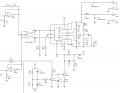
I am trying to repair a pair of Mackie CR3 active speakers which seem to mute shortly after powering up.

The circuit is based around a TDA7265 amplifier IC (see attached). I have been trying to trace the mute circuitry from the IC but noticed D1 and Z2 have different symbols with the same part number (IN4148)? One is a standard diode symbol and the other a zener diode symbol.

I asked Mackie (LOUD Technologies) about this anomaly but they said they can only give out information about schematics to authorised service centres!
 

Attachments

Dodgydave

Joined Jun 22, 2012
11,395
Pin 5 Mute, is muted ( sound off) by connecting to Vss, and unmuted (sound on) by connecting to gnd.

I would disconnect pin 5, and wire a switch to it.
 

TwoBrews

Joined Mar 6, 2019
2
Pin 5 Mute, is muted ( sound off) by connecting to Vss, and unmuted (sound on) by connecting to gnd.

I would disconnect pin 5, and wire a switch to it.
I had a go at disconnecting Pin 5 just so see if this would quickly sort out the issue (I had a similar problem as OP)

However rather than muting the sound it now makes a horrible loud humming as a result.

Just wondering what your thoughts were on this and whether it would be a good idea to replace the TDA7625 or whether the loud hum could be a signifier of another component gone bad within the circuit?

I've only just started looking into repairing some of my broken equipment so any pointers much appreciated!
 

pmd34

Joined Feb 22, 2014
529
Could you test to make sure there is actually a signal going into the TDA7265 (pin 7 & gnd.. pin 11 & gnd)? Use a small (low power) earphone speaker and connect it to the input of the chip, to see if it is something before or after this point that is causing the problem.
 

TwoBrews

Joined Mar 6, 2019
2
Could you test to make sure there is actually a signal going into the TDA7265 (pin 7 & gnd.. pin 11 & gnd)? Use a small (low power) earphone speaker and connect it to the input of the chip, to see if it is something before or after this point that is causing the problem.
I'll give that a try thanks!
 

ChrisVal

Joined Apr 21, 2021
2
I fixed this speakers many times, different problems :
- Sound very bad : 2 big 4700 uF capacitors to be changed (good idea to change them every two or three if you leave fallaways on your CR3 or CR4)
- Wrong contact in Powered speaker position : unsolder the selector and short as on picture
- No more sound :
* Pin 5 is an input of the TDA7635, so no need to change it if you want to fully repair CR3, CR4 )
* First check and clean the headphone plug, you could cut pin 5 of the TDA7265
* Second, change Z3 and/or Z4 (12v Zener) (It is the problem when after cutting pin 5 you ear a big sound mixed with the music).
2 big 4700uF capacitors.jpgLeft Right selector.jpgZ3 Z4 1.jpgZ3 Z4 2.jpg
 

Attachments

Jon Hoover

Joined Oct 10, 2019
34
It just makes me sad when I see discolored areas on a circuit board that are not related to a part failure. It shows that the product is not designed to handle the current very well. A commercial grade speaker should, in theory (in my opinion), be able to be run at full (undistorted) power continuously for days without overheating as long as the ambient air is 40C or below. It also is an indication of the expected longevity of a product when you see many, many repair questions related to a specific product listed in a number of electronics forums.
 

ChrisVal

Joined Apr 21, 2021
2
It just makes me sad when I see discolored areas on a circuit board that are not related to a part failure. It shows that the product is not designed to handle the current very well. A commercial grade speaker should, in theory (in my opinion), be able to be run at full (undistorted) power continuously for days without overheating as long as the ambient air is 40C or below. It also is an indication of the expected longevity of a product when you see many, many repair questions related to a specific product listed in a number of electronics forums.
I agree with you, the Mackie CR3 and CR4 products are inexpensive, well designed, but not made to last too long.
 
ChrisVal - YOU are an Ace! Thank you for not only your different repair scenarios but for your photos and schematics. Thank you for helping me repair these cheap-ass speakers!
 

timmmay

Joined Mar 10, 2025
1
Old thread, but I want to chime in with my observations after repairing my set of speakers that were long overdue for an overhaul.

1) Obviously as others have said just eliminate the speaker position selector switch and bridge the vias with jumper wire looped into a U. A better quality DPDT would solve the problem but most high end thermally insulated heavy duty switches are not side selectable so you would need to rework and bridge the vias at 90' for, say, an industrial NTT switch.

2) Instead of cutting pin 7 and messing with the diodes at Z3/Z4, just have a 3.5mm plug on hand to insert and remove when powering on the speakers. I realize this could be really inconvenient in some cases, but in most cases, people will have one lying around, and in my case, I never turn the speakers off, so the IC rarely needs the input triggered.

3) Another flaw that doesn't get much attention are the RCA jacks. If you are like me and have had a set of RCA plugs with a death grip, there is a good chance you have weakened the connections. Solder and reinforce the RCA jacks while you have the speakers apart.

4) Clean connections, especially the passive speaker connections, with CAIG deoxit or similar. I noticed corrosion in mine because the factory wire for the passive speaker is not very good quality and causes oxidation over time. This was the singular cause of volume imbalance between the active and passive radiators in my case.

5) Whenever reworking a component, be it removing the speaker position switch, RCA jacks or capacitors, remove all old solder with a sucker and wick, and flow in new solder that is 60\40 or ideally 62\36\2 (silver) to prevent future corrosion. Again, remove all old solder first as these are ROHS compliant and solder is lead-free...do not mix chemistries as it will result in a weak joint.

6) While the primary stage capacitors (35v@4700uF) are the main culprit to sound muffling and distortion I have found a full recap really breaths new life into these speakers. Interestingly, at least with my recap, it also eliminated idle hiss. I used Panasonic FC and Nichicon FM where I could, some of the sizes are not available from Mouser, but remember you can always go up on voltage as long as capacity rating is the same. Increased voltage handling means a larger capacitor so in tight spaces you may need to get creative with placement. Where I couldn't source FC and FM I used FW's as they are available in every size and have similar ESR and longevity, not to mention they are super cheap averaging 25 cents each. Most economical caps are all going to be +/- 20% and rated at least 85F. I don't see value investing over $50 in high end ELNA or capacitors or wasting money on overpriced Wurth Elektronik capacitors when I feel Rubycon, Nichicon and Panasonic are superior and far less expensive.

Full capacitor list for the CR3's:
2x 35v 4700uF (these are the most failure prone cap so I went with slightly oversized 50v 4700uF KW's, they were $5 for a pair.
1x 100v 4.7uF
1x 100v 8.2uF
15x 50v 10uF
2x 10v 220uF (I oversized these to 16v 220uF 105C 5000hr HF's due to their proximity to the power transformer heatsoaking)
1x 50v 47uF
2x 16v 100uF
5x 50v 1uF

Overall this is about 1.5hrs work so its up to you if a full recap is worth it. Personally most people would be satisfied with the 4700uF replacement and selector switch delete, but I didn't want to open these things ever again as they are not the most beautiful place to work and the PCB is not very good quality so I'm not sure how much rework it can handle before you start ripping pads. If your PCB is heavily heatsoaked, you may already run into issues of pulling pads so that's another thing to consider "if it aint broke dont fix it"

Cheers!
I agree with recapping. Mackie used really cheap electrolytics in these. Besides replacing the big power supply 4700 uF caps, beware C37 and C38, the 1 uF caps from the left/right slide switch that go to the power amp chip inputs. They both failed on mine measuring 0 and .009 uF, respectively. This caused a really weak, tinny left channel, and a usable, but weak right. I used film caps for these, since they are only 1 uF, are small and cheap enough in non electrolytics, and won't age as poorly as electrolytics do. Also watch that 4.7 and 8.2 uF. They have to be non polarized caps.
 
Top