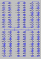
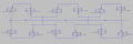
So, I'm currently trying to simulate a solar panel (datasheet is in attachments) in LTSpice. I posted the screenshots below of my schematics I drew and also put the LTSpice file in attachment. Now the simulation works great without the bypass diodes, but when I implement these bypass diodes the results are much lower. The bypass diodes are just normal diodes but when I use zener diodes the results are even worse, no matter what parameters I give. The parameters of the zener diodes used in the picture are: average forward current = 20A and the breakdown voltage is 30V. I'm no expert with these bypass diodes, so is there anyone who can help me with this problem?
without bypass diodes:

with bypass diodes:

with zener diodes as bypass diodes:

Kind regards
August
without bypass diodes:
with bypass diodes:
with zener diodes as bypass diodes:
Kind regards
August
Attachments
-
603.1 KB Views: 3
-
 165.5 KB Views: 11
 -
 62.8 KB Views: 10
 -
11.9 KB Views: 3