Facebook
 Google
 GitHub
 Linkedin
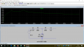
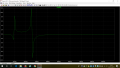
Hi everybody. Just learning by my self some electronics for hobby. I try to plot the LTspice circuit I have here attached but it spits out a plot totally different from the one the text book shows. What am I doing wrong? Thank you and many regards.
Attachments
-
 90.3 KB Views: 11
 -
1.2 KB Views: 4
-
 91.1 KB Views: 11