Lowest possible component count, simple transistor amplifier.

Audioguru again

Joined Oct 21, 2019
6,826
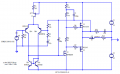
I turned around the backwards diodes but without any negative feedback the distortion was still awful. Then I added negative feedback and the distortion is reduced.

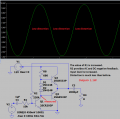
The maximum (before distortion) output power is only 1.1W because the 12V supply voltage is low and the 8 ohms speaker impedance is high.
 

Attachments

Yea, memories.

Car radio amps with the DS-501 transistor.

My father used to repair car radios that he would get from people at work. He didn't quite understand transistors and I was just a kid, so guess who got to fix them.

There was this shop not to far from home where a guy with a prosthesis arm would be taking out and repairing radios. We got our parts there. It was amazing.
 

Ian0

Joined Aug 7, 2020
13,132
@john1211 , I hope you're still following:
If you start with the original circuit posted on the internet (post #20) by an idiot who can't even get the diodes right way round, then correct it (post #21) and then improve it you get @Audioguru again 's circuit in post #22.
If you compare that circuit with the one in post #17, you will see that Q1, Q2, Q3, R4 and R2 in post #22 correspond to U3, U1, U2, R1 and R3 in post #17.
I have taken a very similar circuit to post #22 (which already has all the expensive parts: power supply, power transistors, heatsinks) and added three cheap transistors costing less than £1 in total.
The cheap transistors provide GAIN in large quantities, and feedback can then be used to reduce the distortion, which is about a thousand times better than the circuit in post #22 (and infinitely better than the circuit from the idiot on the internet)
 

BobTPH

Joined Jun 5, 2013
11,523
I still think I gave the best answer to the TS’s question in post #15. Look at what he said.
you have any minimal component designs which can put out about 5 watts up to 10 watts, or if this is not possible a two stage amplifier consisting of a driver transistor followed by an output transistor, again minimal components.
He was asking for a one transistor amp if possible to put out 5W. There was no requirement that it be Audiophile quality, or efficient. The overriding concern was component count.

I believe he wanted a circuit which he could understand and was frustrated with what he was finding. I can explain my circuit to a rank beginner easily.

I considered a class C amp, but that would be cheating because it only amplifies half of the input waveform. So class A was the obvious solution.

A second purpose of my post was to teach that one should be careful what they ask for. The result of his request was a totally impractical circuit that uses 288W to produce 5W of output. But scale it down by a factor of 10, to 500 mW, and it becomes practical.

Bob
 

Ian0

Joined Aug 7, 2020
13,132
I still think I gave the best answer to the TS’s question in post #15. Look at what he said.

He was asking for a one transistor amp if possible to put out 5W. There was no requirement that it be Audiophile quality, or efficient. The overriding concern was component count.

I believe he wanted a circuit which he could understand and was frustrated with what he was finding. I can explain my circuit to a rank beginner easily.

Bob
or you could argue that the salient point was:
I want to learn and get my hands dirty and build my own, for educational purposes.
(my italics)
 

BobTPH

Joined Jun 5, 2013
11,523
Yes, but building a circuit you do not understand does not facilitate that learning.

My plan was to scale it down to a reasonable power so he could build it and get something to work. Then point out the problems with it and how they are addressed, in small steps. The next step would be a class B amp with horrible distortion, then on to AB.

My wife calls this the “win one early” method of teaching.

The first audio amp I made that could drive a speaker used a TO3 power transistor in a class A amp, and I was quite proud if it, even though it would burn your finger if you touched it and killed batteries in a nanosecond (slight exaggeration.)

Bob
 
Last edited:

Audioguru again

Joined Oct 21, 2019
6,826
The original circuit used an obsolete 2SC5200 transistor rated at 230V, 15A and 150W.
It can easily produce 5W or 10W into a speaker if the signal source has a low impedance.
 

MaxHeadRoom

Joined Jul 18, 2013
30,671
Last edited:

Ian0

Joined Aug 7, 2020
13,132
The parts on the schematic in post #17 are so far apart that the text part numbers and values cannot be seen:
Untitled 4.png
Now we have a circuit that basically is a power op-amp, with the bases of the BCM857B being the inputs, and the sources of U1/U2 the output; R8/R4/C7 is the usual feedback network for a non-inverting amplifier.
 

Ian0

Joined Aug 7, 2020
13,132
@Ian0 What do C1 and C3 do?
C3 is the bootstrap capacitor. If you look at @Audioguru again 's circuit in Post #22, you can see it as C4 in a simpler context.
It keeps the voltage across R3 reasonably constant, and that makes R3 into a constant(ish) current source.
R1/R3/C3 can be replaced by a transistor current source which would give some improvement in performance, but the challenge here was low component count.

This is a three stage amplifier Q6= first stage, U3=second stage, U1/U2=third stage.
Each stage can add almost 90° phase shift. If there is any gain when the phase shift reaches 180° it will become and oscillator not an amplifier. C1 reduces the high-frequency gain, so that there is no gain left at the point the phase shift reduces 180°, or, put another way, makes sure that the phase shift is <180° at the point the gain reaches 0dB.
 

Audioguru again

Joined Oct 21, 2019
6,826
Ian, thanks for making your schematic very clear.

The bootstrap capacitor has a DC voltage across it which allows its positive terminal to swing above the supply voltage, increasing the NPN or N-channel positive base or gate voltage swing which increases the maximum output power. Its action as a current source provides a high impedance and a high open-loop gain which lets the negative feedback reduce distortion even more.

I have never designed or made a Mosfets amplifier because of the wide range of Vgs requiring matching or adjustment.
 

Ian0

Joined Aug 7, 2020
13,132
I have never designed or made a Mosfets amplifier because of the wide range of Vgs requiring matching or adjustment.
Thanks for completing the explanation of bootstapping for the benefit of the TS is he's still around.
I have a couple of designs for MOSFET amps which eliminate the need for adjustment, I'll post them later: they might not exactly fit the remit of "minimum component count" <deleted> I'll also try to make sure SPICE exports a nice clear image!
 
Last edited by a moderator:
Top