Low Voltage Battery Alarm and Disconnect 12v

Thread Starter

trader007

Joined Feb 27, 2010
249
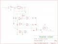
I have a computer in my car, and i would like to leave my computer on with the engine off yet not have to worry about a battery thats not charged enough to start the car. most budget low voltage disconnects you buy have a very low voltage cut out. this is selectable in a range that will work for a variety of purposes. in my case, i think 12.0v would be about right.

the capacitors at the input for the alarm are an attempt to keep the voltage constant while cranking the motor. i dont know if i will need more capacitance there or not.


what do you guys think? im not an engineer so im sure there are better designs, but this one is based of parts you can buy at radio shack so that does make it nice for convenience. will this actually work too? i just dont have the time to try it, maybe soon though.
 
Last edited:

Thread Starter

trader007

Joined Feb 27, 2010
249
is this a little bit too complicated for this forum? ive been trying to find a place that talks about circuits like this one, i just havent had much luck.
 

tom66

Joined May 9, 2009
2,595
A simpler circuit would use a comparator and a relay (getting rid of the 555). If you delay the comparator using a capacitor, it will give you several seconds to crank the engine before it shuts off.

Also, 0.1 farads... are you sure that's the right value?
 

Thread Starter

trader007

Joined Feb 27, 2010
249
i really dont know what i need there. that cap is just to keep the voltage stable during engine cranking. the 555 timer is there to have a delay from when the moment the voltage drops to low, to when the relay actually clicks off.

i wanted at least 2min for this duration, up to 10min ideally- and that can be changed by adding more capacitance at C1
 

Thread Starter

trader007

Joined Feb 27, 2010
249
I don't think I would use that circuit. Where did you get that circuit?
i made it up. and like i said, im not an ee either. that bad?

edit- all these parts are still available at radio shack, i forgot to mention... so thats really why its unique. i know there would be more robust chips to use...
 

JoeJester

Joined Apr 26, 2005
4,390
My first advise is to gather the specifications on what you want to you. The LM-339 comparator listed in your parts list, the output is open collector.

We know you want to latch the 12V to the inverter and have a graceful exit plan on the computer when the battery power get's below a certain value. Doesn't your laptop screen dim slightly when your on battery power vice AC power? Your laptop batteries can proved the grace period you want and that would simplfy the circuit to the comparator and the relay.

How much power is your inverter?
 

JoeJester

Joined Apr 26, 2005
4,390
Upon one nights reflection, you are using a quad comparator. Why not just use two of the four comparators so you can have two different setpoints. One for an audible alarm (available at RS) for lower than 12V levels and and one to disconnect the load (inverter).

Use a 7805 to power the LM339 and two resistors to scale down the 12V source to a usable level.

on edit ... corrected LM339 vice LM449 in the second sentenance.
 
Last edited:

BMorse

Joined Sep 26, 2009
2,675
The Inverter I use in my truck to power my Carputer, has an alarm already built in for when the power from the battery gets too low..... I had tapped into that alarm output to rig an electronic switch to power down the PC when it goes off....

B. Morse
 

Bosparra

Joined Feb 17, 2010
79
I built a similar circuit to this a while ago. I don't have the schematic with me right now, will try and post it later. Basically, an LM358 dual op-amp as two comparators. I used a 5v6 zener as reference and voltage dividers to scale down the sensed voltage.

First comparitor light a battery low indicating LED and the second comparitor switches the power transistor off, disconnecting the load.
 

Thread Starter

trader007

Joined Feb 27, 2010
249
Upon one nights reflection, you are using a quad comparator. Why not just use two of the four comparators so you can have two different setpoints. One for an audible alarm (available at RS) for lower than 12V levels and and one to disconnect the load (inverter).

Use a 7805 to power the LM339 and two resistors to scale down the 12V source to a usable level.

on edit ... corrected LM339 vice LM449 in the second sentenance.
i want to try to do this. i had the same thoughts when i first did this but the people helping me thought the separate timer chip was better for some reason that i dont know.

I built a similar circuit to this a while ago. I don't have the schematic with me right now, will try and post it later. Basically, an LM358 dual op-amp as two comparators. I used a 5v6 zener as reference and voltage dividers to scale down the sensed voltage.

First comparitor light a battery low indicating LED and the second comparitor switches the power transistor off, disconnecting the load.
yes! please post. that sounds like almost exactly like what i am trying to do too.
 

JoeJester

Joined Apr 26, 2005
4,390
If they thought the timer was a better idea ... they should have explained the "why" it is better.

Two comparators is the way to go, since you are controlling the "disconnect" by battery condition (voltage) and not time.
 

Thread Starter

trader007

Joined Feb 27, 2010
249
the problem i forsee though is that it is already going to be hard enough to tweak the voltage point where i want it to set the alarm off... at least with the timer i only have to set one voltage point and thats it. i know using the comparator to work off two voltage points makes a more simplified circuit, but the way i have it now would make it easier to use.
 

JoeJester

Joined Apr 26, 2005
4,390
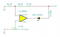
It's easy to tweek the voltages. With two comparators, you have one for the "alarm" condition ... using a piezo device or an LED. The condition can be set with a Potentiometer or two resistors. The same for the scaled down reference voltage.

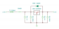
To ensure the decreasing battery voltage doesn't affect the "decision" circuits, the comparators, you can lower the Vcc for the comparator to 5.0 volts using a LM7805.

I'll have to look at radioshack to see what parts they carry to create a Bill of Materials.
 

Thread Starter

trader007

Joined Feb 27, 2010
249
you know, i really dont know why ive held onto the 'radioshack' theme for so long. its just sort of what i started with, but by now i already have a bin of parts from electronic suppliers that totally outclasses what radioshack has anymore. there really is no need to stick with radioshack parts, the only problem is that basically means my drawings are worthless.
 

BMorse

Joined Sep 26, 2009
2,675
Here is a circuit I used in several carputer installs I have done for inverters without a low battery voltage warning....

You can add a piezo at the output for LED1 if you need an audible alarm, (possibly run it through a 555 for a beep alert rather than a continuous sound)

Car Battery Monitor.png

All components can be bought at RS if needed, but most hobbyist should have these in their parts bins.... The relay used is an Automotive type relay, should be rated for the current draw of the inverter... the voltage regulator is an 8 volt one...

B. Morse
 

JoeJester

Joined Apr 26, 2005
4,390
The parts count can be reduced significantly by using a zener as reference, instead of the 7805?
It could, but how does the alternator noise affect the circuits ... you could get false alarms/shutdowns. A marginal battery being recharged and a noisy alternator (electrical) could generate false warnings.

This does not mean the user should drive and use the laptop, but that doesn't preclude someone else from using a laptop while driving.

Besides, 5V/10k is alot easier on the mind than 5.1V/10k. :)
 
Top