Low Power Class AB Amplifier

Thread Starter

RRRRSSSS

Joined Jun 16, 2023
128
One thing to measure in all your sims, that is quite important, is the output transistors' DC bias current with no signal.
My sim of Mr. Al's circuit showed over 3A, witch is obviously way to high.
That current still gives a nice AC output but will dissipate a lot of excess power.
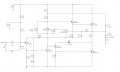
Yes that is really high my bench supply would probably melt.
 

Thread Starter

RRRRSSSS

Joined Jun 16, 2023
128
You have the first transistor as a 2N3906, which is PNP, it is supposed to be 2N3904 (NPN). Works a lot better with that change.
Thanks BobTPH. I made the change.
Sim results:
Vout = 0.42 volts
Vin = 0.5 volts
Gain = 9.72
THD = 0.53%
 

Ian0

Joined Aug 7, 2020
13,158
Here is a sim of the circuit in post #33. I probably have errors since the schematic was
distorted on my screen making it hard to read some component values.

vin = 1 volt
Vout = 0.42 volts
gain = 0.42
THD = 1.57%
I get a gain of 9 and about the same THD as you do.
The .asc file says that Q1 is 2N3906 which is PNP. I replaced it by a 2N3904.
Open loop gain and distortion are about 200 and 44% respectively, so 1.5% is to be expected when feedback is applied.
As is stands it is pure class-B, but increase the bias by increasing RB4 to 470Ω and it comes down to less that 1%, but I don't know how that bias will behave as it gets warm.
 

Thread Starter

RRRRSSSS

Joined Jun 16, 2023
128
I get a gain of 9 and about the same THD as you do.
The .asc file says that Q1 is 2N3906 which is PNP. I replaced it by a 2N3904.
Open loop gain and distortion are about 200 and 44% respectively, so 1.5% is to be expected when feedback is applied.
As is stands it is pure class-B, but increase the bias by increasing RB4 to 470Ω and it comes down to less that 1%, but I don't know how that bias will behave as it gets warm.
I misread the schematic initially as it is blurred so ya Q1 s/b 2N3904. I did increase RB4 to
470Ω the bias went from 1.54 mA to 1.53 mA.
 

Ian0

Joined Aug 7, 2020
13,158
I misread the schematic initially as it is blurred so ya Q1 s/b 2N3904. I did increase RB4 to
470Ω the bias went from 1.54 mA to 1.53 mA.
If you look at the waveform on the collector of Q1 you will see that changing RB4 makes a big difference to the amount it has to jump between top and bottom halves of the waveform. It's still in class B, but it's probably safer because it won't suffer thermal runaway.
 

Thread Starter

RRRRSSSS

Joined Jun 16, 2023
128
I misread the schematic initially as it is blurred so ya Q1 s/b 2N3904. I did increase RB4 to
470Ω the bias went from 1.54 mA to 1.53 mA. If I decrease the value of RB3, the bias
current increases. Not sure how high the bias current should be.

I am not sure why it is operating as class B instead of class AB. The top and bottom
emitter-followers should be turning off and on alternately but how can you determine if
they are do that in a sim?
 
Last edited:

BobTPH

Joined Jun 5, 2013
11,560
The sim works perfectly for me. It has a bit more distorted than the original transistors, but otherwise performs as expected.
 

BobTPH

Joined Jun 5, 2013
11,560
It is working as AB. With the original resistor, the idle current was only about .5mA. Increasing it to 470 it goes to 4.8mA idle current with distortion of 0.42%.

You may note that I said that resistor would need to be tweaked when I said to try it with TIP31 transistors.

With my original transistors, the bias current is 18.8mA and the distortion is 0.13%, and the gain is spot on 10.
 

Thread Starter

RRRRSSSS

Joined Jun 16, 2023
128
It is working as AB. With the original resistor, the idle current was only about .5mA. Increasing it to 470 it goes to 4.8mA idle current with distortion of 0.42%.

You may note that I said that resistor would need to be tweaked when I said to try it with TIP31 transistors.

With my original transistors, the bias current is 18.8mA and the distortion is 0.13%, and the gain is spot on 10.
I changed RB4 to 470Ω and the bias current stayed at 1.53mA. I have attached my sim. There must be
a difference in our spice models or something different.
 

Attachments

BobTPH

Joined Jun 5, 2013
11,560
I do not have models for TIP31 and TIP31 A, I used C, which is a 100V version, but should otherwise be very similar.

With your .ASC I get 4.8 mA of bias current, gain of 9.7 and distortion 0.42%. Which is actually good for this simple an amplifier, though the MJE3055t got me 0.13%. Don't know why it is so much better, I only chose that one because I had it on hand!
 

Thread Starter

RRRRSSSS

Joined Jun 16, 2023
128
I do not have models for TIP31 and TIP31 A, I used C, which is a 100V version, but should otherwise be very similar.

With your .ASC I get 4.8 mA of bias current, gain of 9.7 and distortion 0.42%. Which is actually good for this simple an amplifier, though the MJE3055t got me 0.13%. Don't know why it is so much better, I only chose that one because I had it on hand!
Now I get 5 mA and yet I didn't change anything. I guess we are good. Thanks!
 

MrAl

Joined Jun 17, 2014
13,722
Hello again,

This circuit from before needed a bias adjustment, however the distortion then isn't quite as good. Changing R22 lowers the bias, so i have a feeling that the original design by Nelson-Jones relied heavily on some arcane specifications of the original transistors of old.
Here is the modification, for now just one resistor. That lowers the quiescent current of the two output transistors to about 7ma.
 

Attachments

Thread Starter

RRRRSSSS

Joined Jun 16, 2023
128
Hello again,

This circuit from before needed a bias adjustment, however the distortion then isn't quite as good. Changing R22 lowers the bias, so i have a feeling that the original design by Nelson-Jones relied heavily on some arcane specifications of the original transistors of old.
Here is the modification, for now just one resistor. That lowers the quiescent current of the two output transistors to about 7ma.
Hi
I am getting 55.3 mA.
RS
 

Attachments

Last edited:
Top