Facebook
 Google
 GitHub
 Linkedin
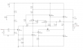
You probably remember from single-transistor amplifiers that the voltage gain is proportional to Gm multiplied by the load resistance.
In this case the load resistance of Q4 is the 400Ω resistor R12.
(R6-R7-Q3 are pretending to be a zener diode, so you can ignore them here)
Assuming that the capacitor C6 remains charged, you can see that the voltage across R12 will remain (relatively) constant.
A constant voltage across a resistance is a constant current. A constant current has a very high impedance (because the current doesn't vary with the voltage). The gain of Q4 is Gm x load impedance. The load impedance is very high because it is a constant current. Therefore the gain of Q4 is much higher than it would be without C6.