Low Pass Filter- Simple ECG

Thread Starter

Gautham Ravichandran

Joined Jan 7, 2018
3
upload_2018-1-7_23-9-19.png
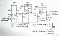
I found this cct diagram for an actice low pass filter for a simple fingertip heart rate monitor. However I dont understand why there is a capacitor in parallel with the 680k resistor aswell as the low pass filter at input. I understand they both have the same correct cut-off frequency but why should both methods be incoporated into the filter - is this to get the best of both worlds?
 

moffy

Joined Nov 13, 2017
11
It is a form of bandpass filter, the first 1u/68k is highpass, the 100n/680k is low pass, hence a bandpass filter. A bit odd though that they have the same time constant.
 

#12

Joined Nov 30, 2010
18,224
The 100nf caps discourage high frequency amplification.
To find which frequency, F = 1/(2 Pi C Xc)
F = 1/( 6.28 x 100E-9 x 680k)
2.34 Hz

Why 2? To create a steeper slope at the high frequency limit.

Edit: The 1uf caps with 68k resistors are high pass filters at the same 2.34 Hz.
That's where the bandpass idea comes to fruition, but it's a very strange thing to make both of them the same frequency.
 

Attachments

Last edited:

AnalogKid

Joined Aug 1, 2013
10,988
This is not a well designed circuit.

First, I question the need for a gain of over 10,000. That kind of forward gain usually comes with some problems.

Second, while the high-pass stages are fully functioning, the low pass stages are not. There is no lower frequency limit to the attenuation curve of the high pass stages. As the frequency decreases the attenuation increases all the way down to infinite attenuation at DC. OTOH, the lowpass stages have a maximum attenuation of 40 dB no matter how high the signal frequency is (until the opamp starts to fall apart). The low pass stages are not filters per se, they are gain stages with selective gain based on frequency. So the max gain is 101 and the min gain is 1, *not* 0.

But the real thing is that two identical (highpass or lowpass) single-pole filter stages in series, even if they are isolated by an opamp to give a controlled low source impedance, are *not* the same as a single, two-pole filter stage. The latter has a sharper "corner" between the pass band and the attenuation slope. As designed there is 75% signal attenuation at the bandpass center frequency.

ak
 
Last edited:

Audioguru

Joined Dec 20, 2007
11,248
EDIT:
If blood flowing in the finger blocks the IR and between heartbeats the finger has no blood so that the IR causes the IR photodiode to conduct then the total gain of 10000 for the opamps is crazy.
The lowpass and highpass frequencies being the same is also crazy.
 
Last edited:

Thread Starter

Gautham Ravichandran

Joined Jan 7, 2018
3
The 100nf caps discourage high frequency amplification.
To find which frequency, F = 1/(2 Pi C Xc)
F = 1/( 6.28 x 100E-9 x 680k)
2.34 Hz

Why 2? To create a steeper slope at the high frequency limit.

Edit: The 1uf caps with 68k resistors are high pass filters at the same 2.34 Hz.
That's where the bandpass idea comes to fruition, but it's a very strange thing to make both of them the same frequency.
Thanks for replying- could you explain why having 2 low pass filters in this active filter (at input as well as feedback) creates a steeper slope for frequencies beyond breaking frequency.
 

AnalogKid

Joined Aug 1, 2013
10,988
First, the input is a highpass filter. The only lowpass filters in your schematic are in the feedback networks.

The predominant characteristic of a single pole lowpass filter is that at frequencies one octave and more below the corner frequency there is essentially zero attenuation, and at frequencies one octave and more above the corner frequency the attenuation increases at the rate of 6 dB per octave or 20 dB per decade. For example, if the corner frequency is 1.0 kHz, then the attenuation is 6 dB at 2 kHz, 12 dB at 4 kHz, 18dB at 8 kHz, 20 dB at 10 kHz, etc. At the corner frequency the attenuation is 3 dB.

If you put two simple, 1 kHz, 1-pole sections in series, everything doubles. The attenuation is 6 dB at 1.0 kHz, 12 dB at 2 kHz, 24 dB at 4 kHz, etc. If you plot this on a logarithmic scale, the transition curve between the flat passband and the straight line attenuation section is very rounded. Specifically, having the input signal attenuated by 50% at the corner frequency is considered undesirable; the whole idea of a lowpass filter is to *pass* the lows, not cut them in half.

A true 2-pole filter section has about the same number of Rs and Cs, but can have very different performance compared to two stacked up single pole sections. This is due to interactions between the two poles. That is intentionally simplistic - the real answer lies in matrix algebra and complex vector calculus, two of the math courses that "separate the men from the boys" in an Electrical Engineering curriculum. A filter has something called a damping factor, symbolized by the letter Q. For a one-pole R-C filter it is fixed. For higher orders it is a parameter that can be manipulated to affect performance in certain areas. Changing the filter's Q changes how it behaves in the region between one octave below and one octave above the corner frequency. You can adjust the damping factor so that the filter is "maximally flat" right up to the corner frequency, a significant improvement over the more simple stacked approach.

Q-factor.gif

https://www.st-andrews.ac.uk/~www_pa/Scots_Guide/audio/part3/page2.html


Note that while the effects of different damping factors extend outward beyond one octave above and below the corner frequency, the most noticeable effects are within that 2-octave band and make for an easier discussion.

Filter design is one of the oldest and most complex (!) areas of circuit design, and the math involved can be flat-out terrifying. There are many different kinds of active filter circuits, each with benefits and problems. Often the problems are in the area of phase response, group delay, time delay, etc. A filter not only attenuates some frequencies more than others, it also takes longer for some frequencies to reach the output compared to others, causing "phase distortion"

https://en.wikipedia.org/wiki/Chebyshev_filter

ak
 
Last edited:

Thread Starter

Gautham Ravichandran

Joined Jan 7, 2018
3
First, the input is a highpass filter. The only lowpass filters in your schematic are in the feedback networks.

The predominant characteristic of a single pole lowpass filter is that at frequencies one octave and more below the corner frequency there is essentially zero attenuation, and at frequencies one octave and more above the corner frequency the attenuation increases at the rate of 6 dB per octave or 20 dB per decade. For example, if the corner frequency is 1.0 kHz, then the attenuation is 6 dB at 2 kHz, 12 dB at 4 kHz, 18dB at 8 kHz, 20 dB at 10 kHz, etc. At the corner frequency the attenuation is 3 dB.

If you put two simple, 1 kHz, 1-pole sections in series, everything doubles. The attenuation is 6 dB at 1.0 kHz, 12 dB at 2 kHz, 24 dB at 4 kHz, etc. If you plot this on a logarithmic scale, the transition curve between the flat passband and the straight line attenuation section is very rounded. Specifically, having the input signal attenuated by 50% at the corner frequency is considered undesirable; the whole idea of a lowpass filter is to *pass* the lows, not cut them in half.

A true 2-pole filter section has about the same number of Rs and Cs, but can have very different performance compared to two stacked up single pole sections. This is due to interactions between the two poles. That is intentionally simplistic - the real answer lies in matrix algebra and complex vector calculus, two of the math courses that "separate the men from the boys" in an Electrical Engineering curriculum. A filter has something called a damping factor, symbolized by the letter Q. For a one-pole R-C filter it is fixed. For higher orders it is a parameter that can be manipulated to affect performance in certain areas. Changing the filter's Q changes how it behaves in the region between one octave below and one octave above the corner frequency. You can adjust the damping factor so that the filter is "maximally flat" right up to the corner frequency, a significant improvement over the more simple stacked approach.

View attachment 143317

https://www.st-andrews.ac.uk/~www_pa/Scots_Guide/audio/part3/page2.html


Note that while the effects of different damping factors extend outward beyond one octave above and below the corner frequency, the most noticeable effects are within that 2-octave band and make for an easier discussion.

Filter design is one of the oldest and most complex (!) areas of circuit design, and the math involved can be flat-out terrifying. There are many different kinds of active filter circuits, each with benefits and problems. Often the problems are in the area of phase response, group delay, time delay, etc. A filter not only attenuates some frequencies more than others, it also takes longer for some frequencies to reach the output compared to others, causing "phase distortion"

https://en.wikipedia.org/wiki/Chebyshev_filter

ak
Ah thanks sorry - stupid of me to think inputs were low pass. I'm currently only in school so yeh looking at complex numbers and the maths behind the filters is probs too difficult. I found this circuit diagram online at http://embedded-lab.com/blog/heart-rate-measurement-from-fingertip/ and apparently it works. I dont understand the values for R and C for the high pass input- surely the cutoff requency for high pass has to be lower at about 1HZ (60bpm).?
 

Audioguru

Joined Dec 20, 2007
11,248
Why are you cutting off heartbeat rates less and more than the normal of 60BPM? Many fit healthy athletes like me have a heartbeat rate down to 30BPM when we are resting but goes up to 180BPM when we work hard. Are you worried about interference from a little insect in the veins of the testing finger?
 

AnalogKid

Joined Aug 1, 2013
10,988
Strictly guessing here, nothing is being cut off. The filter is extracting a frequency component of the pulse that is common to all heart rates. If you look at an ekg, the thing that changes most between low and fast heart rates is the spacing between pulses, not the shape of the pulse. Yes the shape changes some, especially at high heart rates, but not as much as the spacing. Therefore, a filter that detects some characteristic of the pulse shape should perform well over a wide range of pulse rates.

ak
 

Bordodynov

Joined May 20, 2015
3,177
Very poor electronic circuit. Input Offset Voltage -2mV - +2mV !
When the offset is negative the operational amplifier is saturated to zero. In this case, the op amp is not in the amplification mode. To pass a pulse, the signal must be positive and greater than 2 mV. Pulses of negative polarity on the photodiode! It is necessary to put additional resistors connected to the power supply at the inputs of the amplifiers. I would use four 130 kΩ resistors (for two amplifiers).
 

Audioguru

Joined Dec 20, 2007
11,248
Very poor electronic circuit. Input Offset Voltage -2mV - +2mV !
When the offset is negative the operational amplifier is saturated to zero. In this case, the op amp is not in the amplification mode. To pass a pulse, the signal must be positive and greater than 2 mV. Pulses of negative polarity on the photodiode! It is necessary to put additional resistors connected to the power supply at the inputs of the amplifiers. I would use four 130 kΩ resistors (for two amplifiers).
I agree that with the opamps biased at ground plus having input coupling capacitors is an awful way to rectify the signal. Also the "below ground" input signals fed to the opamp inputs could damage them.

EDIT: It is normal in this circuit to reverse bias the photodiode then it conducts leakage current when it becomes lighted.
 

GopherT

Joined Nov 23, 2012
8,009
The device is NOT and ECG. It is, as the OP called it, a simple fingertip heart rate monitor. The jpg's title is, "heartfingermonitor.jpg".

The device is counting heart rate, not outputting an ECG.

It is read by a PIC628A and likely sends output to a seven segment display. He hopes for saturation of this amplifier to get a count during his collection period (I assume the PIC input is a simple counter (clock input)).

Also, these types of sensors rely on the dilation of arteries and capillaries when the heart is beating. More red blood cells in the path of the IR beam of the finger tip vs. between beats. The effect is quite small (in the range of 1%
and will likely get saturation for any 50% delta in blood pressure.

upload_2018-1-9_10-3-53.png

The gain is not 10000, it is 2550.5 max in the passband. Still kind of high but they want high sensitivity.
Bandwidth about 1Hz to 4Hz roughly.
"2550 max" is right. I calculate ~625 for the two stages because of the overlapping high pass and low pass filters.


Also the "below ground" input signals fed to the opamp inputs could damage them.
The MCP602 was likely selected because it can handle the small negative input voltage when used in a single supply application. See datasheet below...

upload_2018-1-9_10-23-44.png

In this case, the op amp is not in the amplification mode.
Of course it is not acting as an amplifier, and nobody wants it to be an amplifier, it is a switch - toggling a digital counter on the microcontroller.
 

MrAl

Joined Jun 17, 2014
11,396
Very poor electronic circuit. Input Offset Voltage -2mV - +2mV !
When the offset is negative the operational amplifier is saturated to zero. In this case, the op amp is not in the amplification mode. To pass a pulse, the signal must be positive and greater than 2 mV. Pulses of negative polarity on the photodiode! It is necessary to put additional resistors connected to the power supply at the inputs of the amplifiers. I would use four 130 kΩ resistors (for two amplifiers).
Hi,

Very good point to bring up. I find the LM358 offset is positive but then that means that the output would be at 0.2v with this circuit. Havent checked the op amp being used here yet.
 

MrAl

Joined Jun 17, 2014
11,396
I agree that with the opamps biased at ground plus having input coupling capacitors is an awful way to rectify the signal. Also the "below ground" input signals fed to the opamp inputs could damage them.

EDIT: It is normal in this circuit to reverse bias the photodiode then it conducts leakage current when it becomes lighted.
Hi,

Yes and op amps dont always respond the way we normally see them respond when they go into saturation, so there is a chance this circuit might not work at all.
 

MrAl

Joined Jun 17, 2014
11,396
The device is NOT and ECG. It is, as the OP called it, a simple fingertip heart rate monitor. The jpg's title is, "heartfingermonitor.jpg".

The device is counting heart rate, not outputting an ECG.

It is read by a PIC628A and likely sends output to a seven segment display. He hopes for saturation of this amplifier to get a count during his collection period (I assume the PIC input is a simple counter (clock input)).

Also, these types of sensors rely on the dilation of arteries and capillaries when the heart is beating. More red blood cells in the path of the IR beam of the finger tip vs. between beats. The effect is quite small (in the range of 1%
and will likely get saturation for any 50% delta in blood pressure.

View attachment 143357


"2550 max" is right. I calculate ~625 for the two stages because of the overlapping high pass and low pass filters.


The MCP602 was likely selected because it can handle the small negative input voltage when used in a single supply application. See datasheet below...

View attachment 143359


Of course it is not acting as an amplifier, and nobody wants it to be an amplifier, it is a switch - toggling a digital counter on the microcontroller.
Hi,

How did you get 625 for the gain?
I did a complete analysis of the entire amp but i'll double check the result i got of 2550.5 in the pass band.

LATER:
Here is the check of the gain in the pass band. Note i am using ideal op amps for theoretical results here.
The top is a plot from pure theory, the bottom is a simulation.
In the bottom plot the green horizontal line is the -3db down point so we can see the bandwidth at a glance.
 

Attachments

Last edited:

GopherT

Joined Nov 23, 2012
8,009
Hi,

How did you get 625 for the gain?
I did a complete analysis of the entire amp but i'll double check the result i got of 2550.5 in the pass band.

LATER:
Here is the check of the gain in the pass band. Note i am using ideal op amps for theoretical results here.
The top is a plot from pure theory, the bottom is a simulation.
In the bottom plot the green horizontal line is the -3db down point so we can see the bandwidth at a glance.
I was trying to simplify. You are correct.
 
Top