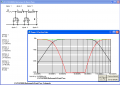
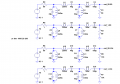
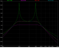
See the attached.
Input/output impedance of 50 Ohms assumed. If yours is different, change it.
I used a Butterworth design for a nice smooth roll-off. It's a bit wider than you asked for, but usually folks want the passband a bit wider. Otherwise, your response at both 33Hz and 100Hz would be 3dB down.
Filter created using AADE Filter Design, available for free here: http://www.aade.com/
[eta]
You're going to have to wind your own toroidal inductors. Amidon's FT-87A in Material "J" (75) should work OK.
Amidon's "J" toroids are on this page: https://www.amidoncorp.com/items/21
The FT-87A-J is the last item on the page; $2/ea
L2 is 245mH; that's 201 turns of wire.
L3 is 200mH; 182 turns of wire.
L4 is 100mH; 129 turns
L5 is 85mH; 118 turns.
Each pass through the center of the toroid counts as 1 turn. Wind it on as evenly-spaced as you can.
Inner diameter of the toroid is only 0.54", so you'll have to use fairly small magnet wire. AWG 28 or AWG 30 would be a good bet, if you're working with line-level signals.
Use poly caps for reliability and better frequency response.
Thanks so much i have been working on this for weeks. Now to find someone to build it for me. I am good with music this is out of my abilitys.
Thanks again
I have an original Vox Crybaby, with the variable Q, that does it all. I don't see any reason to reinvent the wheel. But as Sarge says, it's a pretty simple matter to design a filter prototype for that. A great filter design tool is ELSIE, which is bundled with the ARRL Handbook. It has a GREAT optimization routine in it.....makes it a snap to twiddle filter parameters.
Mik3,
Those are RC filters. While much easier to build than LC filters, our OP will require an active amplifier to boost the signal back up to where it's supposed to be. A properly tuned LC filter won't lose much of the passband signal at all; a mere fraction of a dB.
Once i have the core covered and i still do not have all the windings on do i keep going back over the first windings????
Help please this is all new to me but fun
Once i have the core covered and i still do not have all the windings on do i keep going back over the first windings????
Help please this is all new to me but fun
At audio frequencies, it's okay to overlap windings, but it becomes a bit more complicated to calculate the inductance. Also, your chances of having some parasitic resonances increases. To be on the safe side, us a smaller gauge wire that you CAN fit on in one layer.
Once i have the core covered and i still do not have all the windings on do i keep going back over the first windings????
Help please this is all new to me but fun
Mik3,
Those are RC filters. While much easier to build than LC filters, our OP will require an active amplifier to boost the signal back up to where it's supposed to be. A properly tuned LC filter won't lose much of the passband signal at all; a mere fraction of a dB.
I made the assumption that the impedance of the circuit was 50 Ohms, which is typical for RF stuff. Without the termination resistors, the filter would be seen as somewhere between an open circuit or a dead short, according to the length of the transmission line. The resistors assure a good match.
If his input or output impedance is not 50 Ohms, he needs to say something.
I made the assumption that the impedance of the circuit was 50 Ohms, which is typical for RF stuff. Without the termination resistors, the filter would be seen as somewhere between an open circuit or a dead short, according to the length of the transmission line. The resistors assure a good match.
If his input or output impedance is not 50 Ohms, he needs to say something.
I was disputing your claim that it has negligible loss. With both ends terminated in 50 ohms, it has 6dB loss in the passband.
With a 50 ohm source and a high-Z termination, or a low-Z source and a 50 ohm termination, it still looks fairly good, and the attenuation is negligible. With a low-Z source and a high-Z termination (typical in audio, but not essential), it looks terrible.
I was disputing your claim that it has negligible loss. With both ends terminated in 50 ohms, it has 6dB loss in the passband.
With a 50 ohm source and a high-Z termination, or a low-Z source and a 50 ohm termination, it still looks fairly good, and the attenuation is negligible. With a low-Z source and a high-Z termination (typical in audio, but not essential), it looks terrible.

 Facebook
 Google
 GitHub
 Linkedin