Low efficiency and high temperature on a mosfet at 65KHz

Thread Starter

HRN88

Joined Jul 21, 2020
24
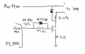
Hi, I´m designing a power supply for a lamp with the FL7701 this is the controller IC. This lamp is for universal voltage from 127Vac to 277Vac. And the output is 30V to 700mA (after efficiency original power input is 25W). I´m using a STM10N60M2 mosfet as a switch, it has 600mOHMS RDS(on) and is capable to deal with 7.5A ID and 650VDS. I´m working with a 65KHz of switching frequency.
My problem is that the mosfet rises a lot of heat: 100-110°C whe input is 277VAC and 70-80°C when input is 127VAC. And my efficiency is low (80% aprox).
I changed Rgate to achieve fast turn on.

Does is normal low efficiency and high temperature on a mosfet at 65KHz?
How can I improve this?
 

Attachments

Papabravo

Joined Feb 24, 2006
21,159
Have you looked at your gate signal with an oscilloscope? If it is spending excessive amounts of time in the linear region because it cannot move charge on and off the gate quickly enough then you would expect the observed behavior. Tall order. With a 15 μsec period you need to charge and discharge the gate capacitance in 7 μsec OR LESS!
 

MisterBill2

Joined Jan 23, 2018
18,179
PapaB is right. The FET is spending way too much time between off and on, which is the linear region. Why not connect the driver directly to the gate? That would be the first thing to try.
Also, examine the drive output specifications of the driver IC, because it may not be able to deliver enough drive if it's power supply is not adequate.
 

Thread Starter

HRN88

Joined Jul 21, 2020
24
PapaB is right. The FET is spending way too much time between off and on, which is the linear region. Why not connect the driver directly to the gate? That would be the first thing to try.
Also, examine the drive output specifications of the driver IC, because it may not be able to deliver enough drive if it's power supply is not adequate.
Yes, In fact I saw VGs with an oscilloscope and it rises in 200ns and fall in 180ns. The FL7701 IC only is capable of drive 200mA at gate driver pin. I have been investigating and I have power switching losses due high frecuency (65KHz), so I tried to down to 45Kz and this improved efficiency and temperature.

By the other hand, could I use a mosfet driver to decrease switching time and loss the heat disipation?
 

MisterBill2

Joined Jan 23, 2018
18,179
Certainly using a correct driver will improve the efficiency a whole lot. Power dissipated during switching has been a problem since the time of germanium power transistors, It is still a consideration with power FETs, because charging and discharging the gate to source capacitance requires moving a lot of charge. So you do need more gate drive with that transistor.
Your other option is to use a transistor that requires less drive, since junction capacit6ance is proportional to current and voltage ratings. So everything is a trade-off.
 

Thread Starter

HRN88

Joined Jul 21, 2020
24
Your other option is to use a transistor that requires less drive, since junction capacit6ance is proportional to current and voltage ratings. So everything is a trade-off.
I will try to do this. Fortunately I have a bunch of mosfets to choose (stock in my work).
A dumb question, a mosfet with a lower Ciss is faster than another with bigger Ciss?
Could I guide me choosing a mosfet with the Ciss parameter in datasheets or should I see the miller plateau (Gate Charge Characteristics).

Thanks a lot:)
 

MisterBill2

Joined Jan 23, 2018
18,179
Typically, but not guaranteed, the lower powered devices are faster. But still the voltage and current specifications must be suitable for the application. So there is always a trade-off.
 

Ian0

Joined Aug 7, 2020
9,677
Have you considered the diode? Unless it is a fast recovery diode, that will be where all the power is going. Rds-on is the least of your worries, 0.6Ω x 0.7A squared is only 0.3W and the transistor is Off most of the time. Use a HIGHER Rds mosfet which has LOWER gate charge. Even so, the switch on time with 47Ω (47Ωx 400pF x 3 time constants) will still be <100ns and should be plenty fast enough.
Is the inductor in continuous current mode? If so, that will hugely increase the diode reverse recovery losses.
 

MisterBill2

Joined Jan 23, 2018
18,179
It should be a simple matter to discover which parts are getting hot, and that is where the wasted power is. Power lost to inefficient operation is mostly converted to heat.
 

Ian0

Joined Aug 7, 2020
9,677
It should be a simple matter to discover which parts are getting hot, and that is where the wasted power is. Power lost to inefficient operation is mostly converted to heat.
True, but reverse recovery problems in the diode will also cause the MOSFET to get hot.

Commenting on a few other points:
1) FL7701 has plenty of drive current, so no need for a driver.
2) To choose a MOSFET: a TO220 package can happily dissipate 0.5W without a heatsink.
The conduction losses will be I^2 x Rds_on x duty_cycle (the duty cycle will be about 0.2)
The switching losses will be about 0.5* Vsupply x I x switching time x frequency
(we assume that the MOSFET will dissipate half the voltage x half the current for the duration of the switching time TWICE a cycle.)
This suggest to me that the switching losses will dominate, and choosing a low gate charge device will be preferred even if the Rds_on is as much as 2 ohms.
 
Top