looking to achieve better mic quality ground loop problem

Thread Starter

Michael_vx

Joined Nov 19, 2021
2
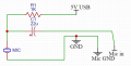
first i would like to apologize for the odd design (not used to make designs yet)
the Idea is using the mouthed being used in Boya M1 mic in a headset
the Plan is to make the Same USB power used for LED on the headset Power the mic
but now we have the shared ground loop problem
and im wondering about how can i get a good use from the 5V USB
and not have to use another power source like a battery ETC the goal is to make the same 2 Jacks (3.5m jacks) + USB jack only
and let the headset get the boost from that
 

Attachments

KeithWalker

Joined Jul 10, 2017
3,063
I don't see anything wrong with the way the microphone is connected. To avoid ground loop problems, just make sure that the microphone common and the USB negative are both connected together at the input common of the amplifier.
usbMIC.jpg
 
Last edited:

Audioguru again

Joined Oct 21, 2019
6,674
Your circuit does not filter the 5V USB so the mic preamp will amplify all the USB noise.
1K is a very low resistor value for an electret mic so it will attenuate the mic output level. Try 4.7k instead.
 

Ian0

Joined Aug 7, 2020
9,674
Then split the 4.7k into two 2.2k resistors, and connect a capacitor between the junction of the two resistors and ground. That will filter out the supply noise.
 

Audioguru again

Joined Oct 21, 2019
6,674
Then split the 4.7k into two 2.2k resistors, and connect a capacitor between the junction of the two resistors and ground. That will filter out the supply noise.
The minimum DC voltage for most electret mics is 2V. A 2.2k resistor feeding a 2.7k electret mic attenuates the signal level to less than half, but a few electret mics have an output impedance of 2.2k ohms so the signal level will be cut to exactly half.
You do not want to attenuate the signal level from a mic unless the signal is from a very loud drum or people screaming.
 

Ian0

Joined Aug 7, 2020
9,674
The minimum DC voltage for most electret mics is 2V. A 2.2k resistor feeding a 2.7k electret mic attenuates the signal level to less than half, but a few electret mics have an output impedance of 2.2k ohms so the signal level will be cut to exactly half.
You do not want to attenuate the signal level from a mic unless the signal is from a very loud drum or people screaming.
The output of an ordinary condensor mic is the drain of a JFET, so the output impedance is in the hundreds of kΩ. The output impedance of a biassed microphone is the value of the bias resistor.
True, if the circuit is used as drawn, then the output voltage with a two 2.2k resistors and a capacitor will be half what it would be with a 4.7k resistor, but it's very rarely used as a voltage output circuit. It is connected to the inverting input of an op-amp, which is a virtual earth. So, the voltage across the 2.2k resistor is constant, and it doesn't contribute to the loading.
 

Audioguru again

Joined Oct 21, 2019
6,674
The output of an ordinary condensor mic is the drain of a JFET, so the output impedance is in the hundreds of kΩ. The output impedance of a biassed microphone is the value of the bias resistor.
True, if the circuit is used as drawn, then the output voltage with a two 2.2k resistors and a capacitor will be half what it would be with a 4.7k resistor, but it's very rarely used as a voltage output circuit. It is connected to the inverting input of an op-amp, which is a virtual earth. So, the voltage across the 2.2k resistor is constant, and it doesn't contribute to the loading.
A condensor mic does not have permanently biased electret material or a Jfet. An electret mic has them.
The impedance at the drain of the Jfet is about 2.7K as I measured some of them.

A higher value drain resistor produces more output voltage swing if it has enough DC voltage fed to it.

I have made many preamps for an electret mic with non-inverting opamps. I have never tried the inverting preamp shown by Texas Instruments.
 

Ian0

Joined Aug 7, 2020
9,674
The microphone specified is an electret condensor.
https://en.wikipedia.org/wiki/Electret_microphone
I always used the inverting amplifier (either bipolar transistor or op-amp).
There used to be both two-terminal and three-terminal microphone inserts. The three terminal types used the JFET in a common drain circuit. They had much better immunity to interference on the power supply.
 

Thread Starter

Michael_vx

Joined Nov 19, 2021
2
I don't see anything wrong with the way the microphone is connected. To avoid ground loop problems, just make sure that the microphone common and the USB negative are both connected together at the input common of the amplifier.
View attachment 253037
there is no amp its from the headset right to the 3.5 MM Jacks of the PC and the USB for the LEDs
the goal is to make as simple as possible with no noise
Your circuit does not filter the 5V USB so the mic preamp will amplify all the USB noise.
1K is a very low resistor value for an electret mic so it will attenuate the mic output level. Try 4.7k instead.
yep mostly the USB 5v is noise is getting on the way i will try the higher resistors and see the results
As a test, power the mic from three or four series AA battery cells to see if it becomes quieter.
using a battery will solve all noise problems because the ground is not shared at all with the power line its now on its own ground and it does work 100% but i dont feel adding a battery to a headset would be a nice idea
 

Audioguru again

Joined Oct 21, 2019
6,674
A USB is full of noise. Your USB noise is not filterd out and feeds directly into the mic audio input.
I said to try a battery because a battery is not full of noise. Of course it shares the circuit ground. If the battery produces no noise then the filtered USB will also produce no noise and shows that the "ground loop" does not exist.
 

KeithWalker

Joined Jul 10, 2017
3,063
You didn't mention before that you were connecting the microphone to a PC. The microphone input of a PC already has a bias resistor built into the circuit. You just need to plug in the mic with no extra power or circuitry.
 
Top