looking for help with a SPDT dip switch

Thread Starter

Barristan67

Joined Dec 26, 2019
2
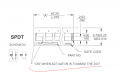
I need a 6 position SPDT dip switch and have been considering using a CTS series part. CTS-204.
The schematic symbol shown is a bit confusing. Is anyone familiar with this part or a similar one that could clue me in on the schematic pinout?

Thanks
 

SamR

Joined Mar 19, 2019
5,031
I don't see a schematic but what I do see for spdt is that the switch handle is double width activating basically 2 switch units at once. And Welome to AAC!
 

MrChips

Joined Oct 2, 2009
30,708
Are you familiar with how pins are numbered on a DIP component?


1577370056829.png

With 6 switches, there will be 4 pins associated with each switch for a total of 24 pins.
For example the first switch on the left will be using pins 1, 2, 23, 24.

Get an ohmmeter and check for continuity across all pairs of pins when the switch is in the two positions.
I am going to guess that pins 2 and 23 are (COMMON) connected and swings between pin-1 and pin-24 for a SPDT switch.
This might not be the same for switches from all manufacturers.

Reference:
http://www.interfacebus.com/dip-switch-diagrams.html
 

KMoffett

Joined Dec 19, 2007
2,918
Tiny schematic for SPDT on page "4 of 8" shows two sets of switch contacts. When one opens the other closes. Not sure if the dashed line indicates that the two sets of contacts are, or need to be, connected to make the single pole function.
 

SamR

Joined Mar 19, 2019
5,031
Yes I saw that small diagram and it's not very clear at all. The dashed line indicates not wired but should be connected. Apparently it is simply 2 switches with a double width common handle? Test it out with a meter to be sure exactly how they are wired as the schematic is not really clear to me. One seems to show only one of the pair of contacts opening/closing. Strangely both SPDT and DPDT have the same part number. so...
 

MrChips

Joined Oct 2, 2009
30,708
Here is the schematic diagram in question.

CTS-204 Switch.jpg

Dashed line usually means that the mechanical mechanism is "ganged". It does not refer to an electrical connection.
I would guess that in one position, pin-1 and pin-24 are open while pin-2 and pin-23 are closed.
In the opposite switch position, pin-1 and 24 are closed while pin-2 and 23 are open.
 

SamR

Joined Mar 19, 2019
5,031
The dashed line for ganged switches usually connects the blades and not the terminals??? Plus the DPST and SPDT have the same part number? so...
 

MisterBill2

Joined Jan 23, 2018
18,167
An SPDT switch is a Single Pole Double Throw switch with three terminals. So that is a bit incorrect for what you seek. Typical multi-pole switches of the slide-switch type, such as record/play switches in tape decks have two parallel rows of pins, equally spaced, with each group of three being a double throw set. (A-common-b), and then repeating along the row. And the numbering is NEVER like on an IC, nor is it like on a dip connector for ribbon cables. Usually it is like the picture in post #6, although the circuit in that picture is strange. The switches in the tape decks were never like that.
Are you hoping to repair something? or building a new piece of equipment? That makes a big difference.
 

Thread Starter

Barristan67

Joined Dec 26, 2019
2
If I had a part on hand I wouldn't be asking these questions.

I found a SPDT from Grayhill (Series 78) that had much better information. It was configured as Mrchips assumed.
I'd rather stick to SMT parts, plus I'd need 2 of these. I'm trying to keep the board small.


This note pretty much confirms that the CTS part is the same configuration as the grayhill part. I'm going to run with it.
1577455347044.png
 

Attachments

Last edited:

Wolframore

Joined Jan 21, 2019
2,609
Ooh nice i gave up looking for these from a project way back, ended up designing a comparator circuit instead to automate the switching. But these are handy! The grayhills look like quality switches.

00BD19E5-0532-49FB-B25F-5689C8AA085D.jpeg
 

MisterBill2

Joined Jan 23, 2018
18,167
OK, now that I see the picture it is clear that I was thinking of the other kind of switches, that have multiple switch sections all transferred by one single actuator. These are totally different. Sorry about the error.
 
Top