Looking for custom made power supply PCB

Thread Starter

engr_david_ee

Joined Mar 10, 2023
211
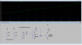
We are looking for adjustable power supply that can be controlled by FPGA/Microcontroller. The output voltage range is 0V to -3V and the load current is 500 mA. The components we need to add in a custom PCB design. Any idea how to achieve it ? An OpAmp can invert the voltage.
 
Last edited:

Thread Starter

engr_david_ee

Joined Mar 10, 2023
211
Clarification on controlled by FPGA/Microcontroller and adjustable.

I am thinking to use Digital to Analog (DAC) with I2C interface on the digital side. This way I can drive and vary the positive Analog voltage controlled by FPGA/Microcontroller and then I need to feed to voltage inverter.

The output voltage range, load current and the input available is the same as mentioned in post 1.
 

Ian0

Joined Aug 7, 2020
10,284
Clarification on controlled by FPGA/Microcontroller and adjustable.

I am thinking to use Digital to Analog (DAC) with I2C interface on the digital side. This way I can drive and vary the positive Analog voltage controlled by FPGA/Microcontroller and then I need to feed to voltage inverter.

The output voltage range, load current and the input available is the same as mentioned in post 1.
If you want a negative output voltage from a positive input voltage, then you need a Ćuk converter
 

Ian0

Joined Aug 7, 2020
10,284
Can you please suggest a a device.
You can make it with a good old UC3842, or any of the more modern devices. Getting the voltage feedback from the negative supply is the biggest problem, but it can be done with the usual TL431+opto circuit that isolated supplies use.
 

ronsimpson

Joined Oct 7, 2019
3,256
Output voltage 0 to -3V.
It is very hard to make a very small voltage with a PWM. As you approach zero volts several things go wrong. Certainly, making 0V is not hard but 0.5V is hard. I have done it but the parts count goes way up.
Can you live with 0V (as in off) and -1V to -3V?
 

Ian0

Joined Aug 7, 2020
10,284
Alternatively, produce a fixed -3.3V with the supply, the Use a buffered op-amp circuit to get the variable output. At 300mA the worst case dissipation is about 1 Watt.
 

Thread Starter

engr_david_ee

Joined Mar 10, 2023
211
Output voltage 0 to -3V.
It is very hard to make a very small voltage with a PWM. As you approach zero volts several things go wrong. Certainly, making 0V is not hard but 0.5V is hard. I have done it but the parts count goes way up.
Can you live with 0V (as in off) and -1V to -3V?
The output voltage between -0.5V to -3.0 V is fine. If 0 V is too difficult.
 

Thread Starter

engr_david_ee

Joined Mar 10, 2023
211
Alternatively, produce a fixed -3.3V with the supply, the Use a buffered op-amp circuit to get the variable output. At 300mA the worst case dissipation is about 1 Watt.
I am wondering about you mentioned buffered op-amp circuit. An operational amplifier in inverting configuration can invert the voltage coming from the DAC/FPGA. I guess it is possible to get voltage between -0.5V to -3.0 V at the output of operational amplifier. What will be the load current capacity ? Usually the output current of operational amplifiers are limited up to 100 mA.
 

Ian0

Joined Aug 7, 2020
10,284
I'm thinking of something like this. V1 is your original positive supply. V2 is the negative supply you have made with the switched-mode. V3 is your reference voltage.Screenshot from 2024-06-11 07-39-40.png
 

Thread Starter

engr_david_ee

Joined Mar 10, 2023
211
I just manage to simulate an inverting operational amplifier. The input voltage Vin can be provided/controlled by DAC/FPGA.

The gain can be adjusted through R3 and R6.

Can it handle the output current 500 mA or 300 mA ?

I guess I need to use a transistor to increase the current.

Untitled 731.png
 

Ian0

Joined Aug 7, 2020
10,284
I just manage to simulate an inverting operational amplifier. The input voltage Vin can be provided/controlled by DAC/FPGA.

The gain can be adjusted through R3 and R6.

Can it handle the output current 500 mA or 300 mA ?

I guess I need to use a transistor to increase the current.

View attachment 324352
It says 310mA peak from a 12V supply, so it can‘t manage 500mA. It is doubtful if it can manage 300mA DC from a 3V supply. It’s also a lot more expensive than a cheap op-amp and a transistor.
 

Thread Starter

engr_david_ee

Joined Mar 10, 2023
211
For some reason, we need to keep the same operational amplifier device. I will connect a transistor to see if it can provide/support 300 mA or 500 mA current for the load.
 

Thread Starter

engr_david_ee

Joined Mar 10, 2023
211
I just manage to simulate an inverting operational amplifier. The input voltage Vin can be provided/controlled by DAC/FPGA.

The gain can be adjusted through R3 and R6.

Can it handle the output current 500 mA or 300 mA ?

I guess I need to use a transistor to increase the current.

View attachment 324352
 

Attachments

Last edited:
Top