 Facebook
 Google
 GitHub
 Linkedin
Hey everyone,
I'm working on a 3 phase motor controller for a 100kw PMAC motor. After many weeks of internet reading and learning circuit/ pcb design I have a rough draft of a single phase I'd like to run by people who actually know what they're doing. My background is in Structural Engineering and this project is just oozing with things I don't know that I dont know... But that's part of the fun!
So my driving requirements (in my perceived order of importance):
- Packaging. Need it to fit in ~9" x 6.5" x 5" box (this is for a motorcycle, very little room in the frame Ive already started welding)
- ~84kw at 168V (500A from battery), plan on hitting up to 100kW in the future.
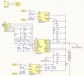
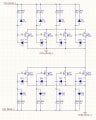
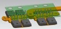
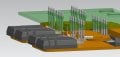
- Im using paralleled mosfets in the inverter so I need to be careful to match the impedance of each half phase's gate pins. (many reasons I'm using mosfets. not really worth discussing, but i really don't want to use IGBTs)
- Need a relatively High switching frequency. Induction of the motor is very low (10.3uH) and consequently people have a hard time driving it. The manufacturers recommend a minimum switching frequency of 16kHz, I'm shooting for 20kHz to be safe
- Everything is going to be very tightly packed... I'm worried about noise screwing with the drivers (inputs and outputs...). Need a smart PCB layout.
- in general want this to be super robust. going to buy high quality components and want any protections possible built into the circuits.
My questions/ concerns are:
A: What about this screams "I don't know what I'm doing"? I'm looking for industry standards, "good practices" I don't know I'm ignoring or any blatant schematic/pcb mistakes you can see. the more the merrier, I'm sure there are lots...
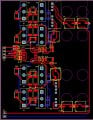
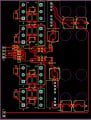
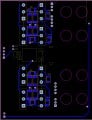
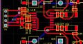
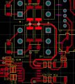
B: The PCB design is super preliminary, but I'd like to know if I'm on the right track or way off base. I only have 20mil traces right now, only one phase modeled but it just looks messy to me.... Its my first PCB so who knows maybe its not too bad... Also, in case its not clear, the mosfet gate resistors and diodes live on both sides of the PCB in the same place to try and make everything more uniform and compact.
C: What should be done about a ground plane and general interference protection on the PCB? I dont have anything modeled because I dont even know where to start. Any idea how worried I should be or know of any good references?
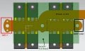
D: With regards to making paralleled mosfets work properly, any thoughts on how I have the power leads connected? Is the gate inductance the main thing to worry about? I have a little CNC mill so cutting sweet copper couplings is no big deal. I'm pretty attached to the Drain plate since it will be my interface with the heat exchangers, but idk if the amount of copper will mess with switching performance (haven't sized the plate thicknesses yet either, these are just estimates)
Thanks! I plan to do more iterations on this, but when i get it working I'll for sure share the plans. Its a fun project.
I'm working on a 3 phase motor controller for a 100kw PMAC motor. After many weeks of internet reading and learning circuit/ pcb design I have a rough draft of a single phase I'd like to run by people who actually know what they're doing. My background is in Structural Engineering and this project is just oozing with things I don't know that I dont know... But that's part of the fun!
So my driving requirements (in my perceived order of importance):
- Packaging. Need it to fit in ~9" x 6.5" x 5" box (this is for a motorcycle, very little room in the frame Ive already started welding)
- ~84kw at 168V (500A from battery), plan on hitting up to 100kW in the future.
- Im using paralleled mosfets in the inverter so I need to be careful to match the impedance of each half phase's gate pins. (many reasons I'm using mosfets. not really worth discussing, but i really don't want to use IGBTs)
- Need a relatively High switching frequency. Induction of the motor is very low (10.3uH) and consequently people have a hard time driving it. The manufacturers recommend a minimum switching frequency of 16kHz, I'm shooting for 20kHz to be safe
- Everything is going to be very tightly packed... I'm worried about noise screwing with the drivers (inputs and outputs...). Need a smart PCB layout.
- in general want this to be super robust. going to buy high quality components and want any protections possible built into the circuits.
My questions/ concerns are:
A: What about this screams "I don't know what I'm doing"? I'm looking for industry standards, "good practices" I don't know I'm ignoring or any blatant schematic/pcb mistakes you can see. the more the merrier, I'm sure there are lots...
B: The PCB design is super preliminary, but I'd like to know if I'm on the right track or way off base. I only have 20mil traces right now, only one phase modeled but it just looks messy to me.... Its my first PCB so who knows maybe its not too bad... Also, in case its not clear, the mosfet gate resistors and diodes live on both sides of the PCB in the same place to try and make everything more uniform and compact.
C: What should be done about a ground plane and general interference protection on the PCB? I dont have anything modeled because I dont even know where to start. Any idea how worried I should be or know of any good references?
D: With regards to making paralleled mosfets work properly, any thoughts on how I have the power leads connected? Is the gate inductance the main thing to worry about? I have a little CNC mill so cutting sweet copper couplings is no big deal. I'm pretty attached to the Drain plate since it will be my interface with the heat exchangers, but idk if the amount of copper will mess with switching performance (haven't sized the plate thicknesses yet either, these are just estimates)
Thanks! I plan to do more iterations on this, but when i get it working I'll for sure share the plans. Its a fun project.
Attachments
-
 136.2 KB Views: 15
 -
 126.8 KB Views: 13
 -
 85.3 KB Views: 14
 -
 164 KB Views: 15
 -
 127.3 KB Views: 15
 -
 114.2 KB Views: 21
 -
 93.9 KB Views: 19
 -
 123.1 KB Views: 16
 -
 78.3 KB Views: 14
 -
 77.6 KB Views: 16
 A few back-of-an-envelope calculations suggested to me that a 15kW PMAC machine would be about equivalent to the 28hp petrol engine in my quad bike.


