Facebook
 Google
 GitHub
 Linkedin
Hello everyone!
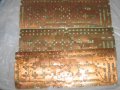
I'm trying to find someone or somewhere that can sell me a bunch of broken / non-functional units of circuitry that are kind of like this..
https://www.ebay.com/itm/1977-1982-...h=item44228ca20d:g:Q7AAAOSw4HlZbPbk:rk:1:pf:0
I would need at least 33 pieces that are of unique appearance and design for this project... I want to use them as art for a physical art edition for a music release I would like to put out..
Any help or guidance at all would be very much appreciated!