Looking for a switch - Which Transistor?

#12

Joined Nov 30, 2010
18,224
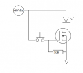
Is this what you have going on right now?

Yes, about 4 volts will turn it on. The 20 volts is the blow-out limit. Give it more than 20 volts and it blows the gate out.
 

Attachments

#12

Joined Nov 30, 2010
18,224
Problem:
Having no resistance in series with the LED will allow it to smoke. Add about 220 ohms (or a bit more) in series with the LED. Possibly as high as 1000 ohms if you don't have many rsistors to play with.

The reason the 10k resistor is needed is that the gate will "float" if it isn't grounded a bit. Besides, the 10k resistor allows the gate to snap back to zero volts when you let go of the switch. I'd add about 22 to 100 ohms in series with the switch so the gate current doesn't surge so hard when you push the button. Keeps the switch from wearing out.
 

Thread Starter

McAdam

Joined Feb 15, 2012
17
Thanks #12

the LED is only there so i can visually see the circuit switching. Ive removed it already :)
I'll try to see if i can find a nice resistor somewhere :)

Thanks a million. Now ive gotta research my next quest. How to limit the circuit to only being on for 15 secs :p
 

#12

Joined Nov 30, 2010
18,224
That's called a "monostable" timer. Go to the top of the page, click on Vol VI-experiments, chapter 8, monostable.
 

wayneh

Joined Sep 9, 2010
18,183
Gate Threshold Voltage 2-4V

I thought that meant that the gate needed at least 2-4v to fully open. Am i mistaken and its actually 20V?
I believe by "threshold" they mean where it just begins to conduct, not where it is fully conducting. The 20v is the max, and "ideal" is about 12V. Fully on, but not close to the max.
 

#12

Joined Nov 30, 2010
18,224
I looked very carefully at the spec sheet and see that this MOSFET will be heating up by about 1.5 to 5 watts. It is not as good as the transistor I chose but it has a duty cycle of 15 seconds on and human time off. I think it will survive. If it doesn't, McAdam will just have to buy a better MOSFET.
 

wayneh

Joined Sep 9, 2010
18,183
... this MOSFET will be heating up by about 1.5 to 5 watts. ...
5W could be a problem. But I don't think we know which MOSFET the OP is using, do we? He couldn't find the P you recommended but didn't come back with another. Using the N in that circuit won't work real well.
 

wayneh

Joined Sep 9, 2010
18,183
Ahh, I see. I think that'll be a problem if the gate voltage doesn't stay high, and it's passing the full 4.5A.

In that picture in post #20, it looks like the power supply is connected to the drain (middle) pin?
 

#12

Joined Nov 30, 2010
18,224
Well, I tried drawing it the other way but was told I did it wrong.

Edit: Disregard. Confused answer.
 
Last edited:

wayneh

Joined Sep 9, 2010
18,183
Well, I tried drawing it the other way but was told I did it wrong.
It'll switch "on" for current flow in either direction, but I believe there is a body diode that conducts in the source-to-drain direction, even when the gate is "off".

If you mean the comment in #10, note that was directed to using a P MOSFET, which this is not.
 

#12

Joined Nov 30, 2010
18,224
I just figured out you asked about a photo, not a drawing.
Sorry, my bad.

As for what is connected to which pin in post#20, I tried to clarify that in post #21. OP said the drawing was right.
Perhaps he will come back and clear this up with you.
 
Last edited:

Thread Starter

McAdam

Joined Feb 15, 2012
17
Ahh, I see. I think that'll be a problem if the gate voltage doesn't stay high, and it's passing the full 4.5A.

In that picture in post #20, it looks like the power supply is connected to the drain (middle) pin?
Well the power source is 11.2A (2 highrdain 18650 Batteries. So so long as the DC-DC converter gets at least 4.5A I'll be a happy man.

The PS is not connected to the middle pin.
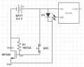
Attached is a circuit diagram of how it currently is.
I just figured out you asked about a photo, not a drawing.
Sorry, my bad.

As for what is connected to which pin in post#20, I tried to clarify that in post #21. OP said the drawing was right.
Perhaps he will come back and clear this up with you.
Hopefully this matches up with what you drew :)
 

Attachments

wayneh

Joined Sep 9, 2010
18,183
Schematic looks OK now as far as switching the IC on and off, but brings back my first concern - the chip is "hot" by being directly connected to +. If the output connects to something that is eventually grounded, I'm not sure what might happen. Read the datasheet, maybe it's OK. Definitely bad form in general to have a hot IC that's not grounded.
Oh, and you'll roast your LED if there's no resistor to limit current.
 

Thread Starter

McAdam

Joined Feb 15, 2012
17
By "HOT" do you mean having power going through while not switched on?

Its only connected to the negative side of the circuit. As in the power flows from battery directly to V in of regulator, then from negative of the regulator to the IC. Then from IC to Battery.

Is this not the best way to wire it in?
How would I avoid having the IC Hot while the button is not pressed.
 

wayneh

Joined Sep 9, 2010
18,183
How would I avoid having the IC Hot while the button is not pressed.
You'd use a p-channel mosfet to switch the high side - as suggested - instead of an n-channel to switch the low side. That way, the IC is always grounded.

Your current circuit arrangement might be fine. It just depends on the IC. If there's no current path thru the IC, from in to out, it'll likely be OK. Only the datasheet can reveal this. Do you have it?
 

Thread Starter

McAdam

Joined Feb 15, 2012
17
ok I see.
My Local electronics store dosnt actually have a search function or datasheets for their MOSFETS. Might have to try and go down to find someone to speak to.
 

wayneh

Joined Sep 9, 2010
18,183
Sorry, I was referring to the DC-DC converter. You need to know if it can tolerate low-side switching. That may depend on what the load is, for instance if there is another power source present. I just looked at the datasheet and it's not clear on that issue. Maybe you could ask the manufacturer. I see there are also a lot of hobby circuits online using this device. Maybe you can find where someone else has used it this way.
 
Top