Facebook
 Google
 GitHub
 Linkedin
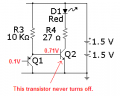
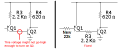
Why is the base current much higher than the max output high current of a Cmos 555 that has a low supply voltage?If they were connected backwards, TP2 for circuit 2 would be a lot higher.Well, it looks to me like it's pretty well saturated. He's only measuring a Vce of 10mV.
Long Duration LED Flashers
- Thread starter Wendy
- Start date
 I now know it can source 1A, or used to be able to.