Long Distance DC Voltage Drop

strantor

Joined Oct 3, 2010
6,875
For polarity reversal buy two modules and use this schematic:
View attachment 141625
That drops another precious 0.5-1.0v and puts a negative 0.5-1.0v across the second module. Can the modules handle a small negative input?.

The other problem putting a booster on the end is that it's not 100% efficient, it draws more power than the motor, and gets less efficient the higher the difference between input and output voltage. It actually pulls the line down voltage down further and further in avalanching fashion. For example (made up numbers) the motor draws 1A and you have 10ohms resistance in the line going to it. 10V are dropped across the line so the motor only sees 14v. Now you introduce the booster, and it steps that 14V up to 24V. 1A × 24V = 24W. Input power to the converter is going be higher because of inefficiency. Lets say its 85% efficient at this given up-step of 14V, so input power to the converter is 28W. Source voltage is 24V, 10 ohms of line resistance, 28W load... so there will be 1.167A drawn from the source, across 10 ohms of line resistance, so 11.67V will be dropped across the line, meaning only 12.33V is available to the converter, which makes it less efficient, which means it will draw more current, which means it will receive less voltage, which means it will draw more current, which means it will receive less voltage, ad infinitum. There will probably some equilibrium reached where it will work, but I don't know that for a fact. Would have to run the real numbers based of the efficiency curve of the converter and it would more math than I'm willing to do. This is a common problem I'm used to having to solve at work, for calculating the conductor requirements for subsea machines in over a mile deep of water and powered from the surface. In that scenario the answer is always to use better conductors and/or step up the supply voltage and use higher voltage components on the subsea equipment. None of that is an option here.


Edit: with the module costing only $1, I suppose it would be worth a try. As long as there's no rush... waiting on shipping from China for something that isn't guaranteed to work
 
Last edited:

Danko

Joined Nov 22, 2017
2,241
That drops another precious 0.5-1.0v and puts a negative 0.5-1.0v across the second module. Can the modules handle a small negative input?.
The other problem putting a booster on the end is that it's not 100% efficient,.........
About negative input see picture below. Your remarks about precious 0.5-1.0v and possible avalanche process are essential and I need work on it.Valve-2.png
 

Janis59

Joined Aug 21, 2017
1,894
The problem is very similar to those I met at early 80ies for stadion loudspeakers and amplifiers. Typically they use some 50-200 speakers for 100W each (yes yes, more than 10-20 kW), so they having no any ultrapower amplifier, use stacks of zillion identical amplifier boxes for 100W in the one room, and huge sized zillion cables from this room to the loudspeakers. Result - speakers are transported by 1 containers, amplifiers by 1 sea container, but cabling with 20 heavy trucks.
And then came a Finns what find that first mosfets was just invented. That means they may organize the amplifiers working not on Vcc=50V but on 314 or 535 Volts instead (what is filtered 220 or 380 output).
So, to each amplifier they economize some 20 kg of steel and some 100 Eur of coins. Plus, those systems are so much uniform, that in their case there was no any problem to connect all those hundreds of boxes brutally parallel. So the cabling tons was shifted away toward the one simple two-wire cable, what works to all loudspeakers in parallel. Yet here they got another problem with output of 300 or 500 Volts, but somehow they managed Americans to wind a million similar ferrite transformers for just about dollar a piece, so there was easy to hide it in each loudspeaker box. So they was proud to diminish the truck count to one alone, carrying all in for stadium events.

Why I am telling this, You may ask, - because why to not feed the motor You have by ordinary 380 Volt cable what is cheapest of all known cables, and in far-end apply the appropriate transformer (with rectifier if needed). Or apply the step-down topologies for DC-DC converting. The benefit will be diminishing of current some 20 fold at least, so Your voltage losses will be 20 fold less what may read as power losses will be 20^2=400 fold less.
 

strantor

Joined Oct 3, 2010
6,875
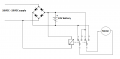
Here's my idea for a battery at the end, and accounting for polarity reversal.
valve ops.png

The power will remain ON (in either polarity) at all times to keep the battery topped up.

The bridge rectifier keeps the power to the battery always steered in the proper polarity.

The relay is energized when power is applied in one polarity, and de-energized when applied in the opposite polarity. The relay steers the polarity to the motor in the proper direction.

The limit switches in the motor will cut power to the motor once it reaches full stroke, and with the power still applied, the battery will "trickle charge."

Care should be taken in selecting a relay with very low coil current at 24VDC.

The power supply is specified 26-29V to overcome diode voltage drop and charging current voltage drop.

EDIT:
This could be a suitable relay. 22mA coil current. this would only cause 0.56V drop if I have calculated your line resistance correctly (25.5 ohms). This 0.56V plus 1.4V (worst case for the bridge rectifier) is 2V. Should work fine I expect.

EDIT2: this one is even better. 12.5mA coil current, and available in quantities of (1).
 
Last edited:

tcmtech

Joined Nov 4, 2013
2,867
Here's my idea for a battery at the end, and accounting for polarity reversal.
With that design the battery could conceivably be replaced with a large capacitor as well. Given the valve motor likely only has to run for a few seconds a several 10's to few 100 's of thousands of uF capacitor would likely give it more than enough on site power to get the valve motor up to speed and stay at speed to the end of travel with the added power still being supplied through the line.
 
Last edited:

strantor

Joined Oct 3, 2010
6,875
With that design the battery could conceivably be replaced with a large capacitor as well. Given the valve motor likely only has to run for a few seconds a several 10's to few 100 uF capacitor would likely give it more than enough on site power to get the valve motor up to speed and stay at speed to the end of travel with the added power still being supplied through the line.
The datasheet says the motor takes 11s to fully stroke. The motor pulls 700mA @ 24V which for simplicity I'll say represents a 39 ohm resistive load.
Simulating a 100uf cap in place of the battery, indicates the cap will drop from 29V to 17.4V (source voltage - line drop, AKA the point at which the cap might as well not even be there) in about 1 or 2 uS.

upload_2017-12-14_9-55-13.png

I replaced the 100uF cap with a 0.1F cap and it took 5 seconds to drop from 29V to 18V (probably around the drop-out voltage of a 24V relay).

I think in order for a cap to work it would have to >= 0.5F (supercap), and rated 30V. It would probably be cheaper to get a couple of lawnmower batteries.


I wonder what happens to this system (whatever this system is LOL - a bit of a mystery) if the valve opens half way and stops. Or if the valve opens half way and then reverses.

I would go with the battery personally.
 

Danko

Joined Nov 22, 2017
2,241
Idea about converter becomes dead because of inrush current of motor which is about 3 times more than nominal current.
Only battery works.
 

tcmtech

Joined Nov 4, 2013
2,867
The datasheet says the motor takes 11s to fully stroke. The motor pulls 700mA @ 24V which for simplicity I'll say represents a 39 ohm resistive load.
Simulating a 100uf cap in place of the battery, indicates the cap will drop from 29V to 17.4V (source voltage - line drop, AKA the point at which the cap might as well not even be there) in about 1 or 2 uS.

Yea, I missed the addition of the thousands of uF on that first post and didn't do the math either. Too early in the morning and did not do a proper proof read either. :(

Given the partial power being supplied I think a pair of 1 F car audio caps stacked in series would do just fine but really I think the whole concept is being over engineered myself. So far no info has been given saying the motor has any sort of actual sensitive electronic to deal with and thus if not just usings higher voltage power source would likely do the job just fine.

I tend to deal in adequately functional not ideal working conditions when solving odd problems. ;)
 
Top