Logic Quandary for analogue circuit

ci139

Joined Jul 11, 2016
2,000
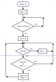
you define your problem some how not "so"
temp-1.png versus temp-2.png gives you boolean expression (L→R,parameters A,B,C)
/// Fn(A,B,C) = A · !(B + C) + !A · !C = A · !C · !B + !A · !C · (B + !B) = (A xor B) · !C + !A · !B · !C =
= { (A xor B) + !A · !B } · !C = { (A xor B) + !(A + B) } · !C the last is Function2
temp-3.png or ... temp-4.png
-----
but what you actually need ? = the logic may be "sequential" / dynamic / time dependent - - try to answer ::
  • What forces you sys. to go into INIT mode
  • What forces you sys. to go out from the INIT mode
  • is there any (multiple) control signals occuring(/transitioning) at very narrow interval ...
    • ... should you delay any of these (in order for hardware to function properly)
    • ... should you define which one prefer over the other (so the system logic would be correct)
    • ... what defines such preference
    • ... etc. ...
 
Last edited:

AnalogKid

Joined Aug 1, 2013
12,167
OK, down to the digits -

Two toggle switches with pull up/down resistors. Or, for extra circuit stability, should the switches be SPDT and drive individual set/reset flipflops? This is the ultimate debounce circuit, but adds one (quad NAND) IC to the circuit.

Circuit operating voltage?

"Output drives NPN transistor" - as in an open collector output? If so, circuit voltage and collector current when on?

I prefer bipolar transistors in industrial applications, but a power MOSFET will get you a lower "saturation" voltage.

Output protection? Inductive kick, overcurrent, negative voltage undershoot, etc..

ak
 

AnalogKid

Joined Aug 1, 2013
12,167
Having achieved the light on state one of the switches (TUNE) can be toggled in any position and the light will stay on.
Easy.
However if the other switch (EN) is toggled to the off position the light will go off.
Tricky. In the INIT state, off/off means the light is on. If Tune is off when EN goes off, does Tune need to go on and off again to return the circuit to the INIT state?

ak
 

Thread Starter

Stretchyman

Joined Sep 10, 2019
21
Er.. Look it's just a couple of switches and the output must go high tis all.

Please forget all the other stuff as it's not important, even switch bounce will not effect it.

Its an analogue circuit being controlled so timing doesn't matter at all.

Please, most replies seem to be somewhat overthought.

I understand it a bit of a strange one and perhaps I've not explained precisely enough.

BUT a NOR with a latch seems close as does a 4098 (dual monostable).

Please no more boolean or questions about power ratings..

Thanks for your thoughts btw, I knew it was a little tricky...

Str.
 

AnalogKid

Joined Aug 1, 2013
12,167
No problem. Closing in ...

Are the switches already wired to pull a signal down to GND when on, or can they pull the TUNE and EN signals high? If they already are wired to switch to GND it's not an issue, just trying to reduce the logic as much as possible.

ak
 

Thread Starter

Stretchyman

Joined Sep 10, 2019
21
No problem. Closing in ...

Are the switches already wired to pull a signal down to GND when on, or can they pull the TUNE and EN signals high? If they already are wired to switch to GND it's not an issue, just trying to reduce the logic as much as possible.

ak

OK, they'd float high when open, down to ground when closed.

Thanks AK.

Str.
 

ci139

Joined Jul 11, 2016
2,000
altough
replies seem to be somewhat overthought
there's an example of ...
should you delay any of these (in order for hardware to function properly)
temp-5.png online simulation (it's required to refresh from attached .txt file Falstad>menu>Import from Text) + a "dynamic response bug" fix for the initial S or R (set) to work temp-6.png . . . the 2-nd .txt ←← the entire circuit is "impractical" but it is good to illustrate the implementation of the "fuzzy" / "peculiar" control signals
 

Attachments

Last edited:

Thread Starter

Stretchyman

Joined Sep 10, 2019
21
I did a sim in an online thing...

but cant post it up...

But to check I'm not going mad could someone sim an RS latch with the EN on the R input, the TUNE on the S input via a NOT gate and the output on the Q.

Seems to do the trick??

Str
 

djsfantasi

Joined Apr 11, 2010
9,237
Don’t you need to run BOTH the Tune and En signals through a NOR gate which has its output fed to the S input of the latch (implemented with a CD4013)? That’s what I was going to draw up.
 

ci139

Joined Jul 11, 2016
2,000
temp-7.gif just add your NOT (right at empty background , click select ... Logic gates I&O .. inverter) the Falstad circuit editing requires the nerves of steel or the total absence of 'em coz you continuously have to dbl-clk elements to force the selection single , also rg-clk the screen-bkgnd and select drag-selected coz it continuously loses activation and there is no kbd shortcut provided for . . . and finally it simulates poorly . . . but it simulates fast the simple circuits and principally "right" enough (. . . mostly !!!)
 
Last edited:

AnalogKid

Joined Aug 1, 2013
12,167
I think I have it all - INIT logic, THEN logic, and the latch - all in one quad NOR. I'll chew on this some more while I finish the lawn.

Again, what happens in the THEN mode when the EN input turns off the lamp. At that time the

ak
 
Last edited:

AnalogKid

Joined Aug 1, 2013
12,167
I think I have it all - INIT logic, THEN logic, and the latch - all in one quad NOR. I'll chew on this some more while I finish the lawn.

Again, what happens in the THEN mode when the EN input goes high and turns off the lamp. At that time, the TUNE input can be either high or low. Please describe each case.

ak
 

djsfantasi

Joined Apr 11, 2010
9,237
I think I have it all - INIT logic, THEN logic, and the latch - all in one quad NOR. I'll chew on this some more while I finish the lawn.

Again, what happens in the THEN mode when the EN input goes high and turns off the lamp. At that time, the TUNE input can be either high or low. Please describe each case.

ak
I agree that your approach is workable! Great reduction!

I still think you're going to need pull-up resistors on the switches. And the NOR gate flip flop is likely going to require a MOSFET driver for the lamp.

Good approach!
 

AnalogKid

Joined Aug 1, 2013
12,167
I agree that your approach is workable! Great reduction!
I still think you're going to need pull-up resistors on the switches. And the NOR gate flip flop is likely going to require a MOSFET driver for the lamp.
I see pull-up resistors and decoupling caps as givens.

Somewhere above he mentions an NPN transistor driving the output. If the circuit runs on 5 V, then AC series CMOS can drive it easily.

ak
 
Last edited:

djsfantasi

Joined Apr 11, 2010
9,237
I see pull-up resistors and decoupling caps as givens.

Somewhere above he mentions an NPN transistor driving the output. If the circuit runs on 5 V, then AC series CMOS can drive it easily.

ak
Post #28 suggests that the TS does not share your opinion on pull-up resistors. That’s why I explicitly mentioned it.
 

AnalogKid

Joined Aug 1, 2013
12,167
Saw that and ignored it. High, low, on, off, open, and closed all have been used with less than consistency. I just added "float" to the list of things that will be cleared up with a schematic. I understand what he is trying to say.

ak
 

Thread Starter

Stretchyman

Joined Sep 10, 2019
21
Yes indeed I have made things a tad confusing and others seem to have contributed.

So I have an SR latch. R, S, Q & Q.

INV (NOT) on the S input, this is the TUNE input

EN input to R.

Output is on the Q output.

Please forget all pull ups, downs whatever, even the driver required for the O/P, it will drive a 10A relay and Yes I know what I'll need for that.

This is an exercise searching for a simple solution, which will be implemented BTW!
 
Top