LM7812 Overheating in Synchronous Buck Converter Circuit

Thread Starter

edward.whittle

Joined Sep 1, 2015
3
Hi All

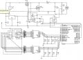
I'm working on a PWM controller synchronous Buck Converter circuit that takes a 24V 1A input and delivers 12V at the output. The PWM signals are sent from a PIC16F887 operating in half bridge mode with a frequency of 5kHz. The circuit simulates correctly in ISIS however when the circuit is built the LM7812 overheats quickly. The purpose of the LM7812 is to deliver 12V to the 741 buffer op-amp for the ADC converter input (steps the output voltage down from 0-24V to 0-5V to be read into the ADC) and the VCC and VB inputs for the IR2014 MOSFET gate driver. I'm stuck as to what is causing this to overheat. Can anyone please shed some light at to how to rectify this problem? The circuit diagram is attached

Kind Regards,

Edward Whittle
 

Attachments

GopherT

Joined Nov 23, 2012
8,009
Put a diode between Your supply and pin 1 of the lm7812, then increase the value of C4 from 1uF to 100 or more uF.
Your supply is likely oscillating like crazy and heating the 7812.

Also, the 2 x 7-segment LED displays are drawing about 0.1 amps and you are dropping 12V across that regulator. That is 1.2 Watts. You should have a heat sink on there at that wattage if you insist on using a 24 V supply.
 

Thread Starter

edward.whittle

Joined Sep 1, 2015
3
How much current does U4 draw?
The operating current of the IR2104 should be no more than 270uA.

Put a diode between Your supply and pin 1 of the lm7812, then increase the value of C4 from 1uF to 100 or more uF.
Your supply is likely oscillating like crazy and heating the 7812.

Also, the 2 x 7-segment LED displays are drawing about 0.1 amps and you are dropping 12V across that regulator. That is 1.2 Watts. You should have a heat sink on there at that wattage if you insist on using a 24 V supply.
Thanks for that advice, I will try that as soon as possible. Will a standard 1N4004 suffice for this? Additionally, I will need to use a LM7805 5V regulator to power the PIC microprocessor and the 7-segment displays which will be placed in parallel with the LM7812. I assume I will need to do the same for this voltage regulator. The supply must be 24V unfortunately so I will need to power the peripherals from this supply as well.
 

GopherT

Joined Nov 23, 2012
8,009
The operating current of the IR2104 should be no more than 270uA.


Thanks for that advice, I will try that as soon as possible. Will a standard 1N4004 suffice for this? Additionally, I will need to use a LM7805 5V regulator to power the PIC microprocessor and the 7-segment displays which will be placed in parallel with the LM7812. I assume I will need to do the same for this voltage regulator. The supply must be 24V unfortunately so I will need to power the peripherals from this supply as well.
The LM7805 will suffer a bit less, it is still putting out 0.1 amps for the two 7-seg displays plus what ever else you have hanging on there but the voltage drop is only 7 volts or 0.7 amps. It may not go into thermal protection mode but it will be hot to the touch.

Yes, if your total load is under 1 amp, a 1N4004 will be fine.
 

Thread Starter

edward.whittle

Joined Sep 1, 2015
3
The LM7805 will suffer a bit less, it is still putting out 0.1 amps for the two 7-seg displays plus what ever else you have hanging on there but the voltage drop is only 7 volts or 0.7 amps. It may not go into thermal protection mode but it will be hot to the touch.

Yes, if your total load is under 1 amp, a 1N4004 will be fine.
Thanks for your help, I will report back with the results
 
Top