Facebook
 Google
 GitHub
 Linkedin
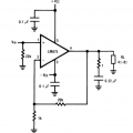
Hi all. I'm currently using the LM675 from TI to construct a non-inverting gain amplifier. I'm currently using the non-inverting gain amplifier schematics provided in the datasheet.

For the +Vcc and -Vee, I'm powering it via two 24V DC power supplies connected in series, hence giving me +24V and-24V respectively. Hence because I'm directly connecting the power rails to the 24V DC power supplies, I didn't include the 0.1microFarad capacitors (as seen in the picture above). For Vin, I'm using my Arduino DUE to supply a 40kHz square wave( from Vmin= -2.72V to Vmax= 2.72V). I'm hoping to amplify this 2.72V input to a higher voltage (preferably to about 20V).
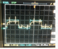
This is the output that I'm getting (measured by my oscilloscope at pin 4(from the figure above), referenced to ground (from the arduino). I'm not sure why my output signal is smaller than my input signal of 2.72V from the Arduino. I've double checked the input signal (from the Arduino), and it is giving me the correct signal.

I've also realized that this output (from the picture above), does not seem to change whether or not the two 24V DC power supplies are turned on. Does this mean that there's an issue with the way I connected my power rails?
Any help would be much appreciated, thank you.
For the +Vcc and -Vee, I'm powering it via two 24V DC power supplies connected in series, hence giving me +24V and-24V respectively. Hence because I'm directly connecting the power rails to the 24V DC power supplies, I didn't include the 0.1microFarad capacitors (as seen in the picture above). For Vin, I'm using my Arduino DUE to supply a 40kHz square wave( from Vmin= -2.72V to Vmax= 2.72V). I'm hoping to amplify this 2.72V input to a higher voltage (preferably to about 20V).
This is the output that I'm getting (measured by my oscilloscope at pin 4(from the figure above), referenced to ground (from the arduino). I'm not sure why my output signal is smaller than my input signal of 2.72V from the Arduino. I've double checked the input signal (from the Arduino), and it is giving me the correct signal.
I've also realized that this output (from the picture above), does not seem to change whether or not the two 24V DC power supplies are turned on. Does this mean that there's an issue with the way I connected my power rails?
Any help would be much appreciated, thank you.
Attachments
-
 39.7 KB Views: 9