Facebook
 Google
 GitHub
 Linkedin
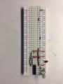
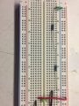
I am trying to use the LM3914 display driver chip, but I am not sure I understand the way it works. I am using an external 1.6V voltage source on pin 6 and have grounded pins 4 & 8 and attached a 1K resistor from pin 7 to ground. My signal source is on pin 5. Pin 2 is system ground and pin 3 is +5V (relative to system ground). If I understand this correctly, my input voltage source should be dropped internally through the 10 1K resistors in steps. So, I would expect that any signal larger than 1.6V should cause all of the comparator outputs to be at +5V. As the signal source drops down I would expect pin 10 to go to ground level at about 1.44V input and pin 11 to go to ground level about 1.28, etc and for pin 1 to go to ground level at about 0.16V.
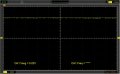
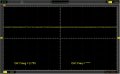
This is not happening. All of the outputs are stuck at +5 no matter what the input signal is. Am I confused about how this chip works? See the attached LM3914 data sheet. thanks, vern
This is not happening. All of the outputs are stuck at +5 no matter what the input signal is. Am I confused about how this chip works? See the attached LM3914 data sheet. thanks, vern
Attachments
-
1,005.1 KB Views: 17