Then the problem is the DC voltage on pin 5.
Don‘t forget that the LM3914 is a DC Voltmeter. If you want to measure any audio signal with it, you first must turn it into DC.
Then the problem is the DC voltage on pin 5.
Don‘t forget that the LM3914 is a DC Voltmeter. If you want to measure any audio signal with it, you first must turn it into DC.
Thanks but I have a Rectifier before and a DC block in serial with the PIN 5 and the problem is till here, I don't have any DC in PIN5 with the DC volt-meter.
I don't have this problem with another 10 LED barmeter.
A small resistor between pin 4 and V- would raise the voltage comparator thresholds slightly, which might shut off LED 1 (at the expense of distorting the meter scale slightly).
Thanks but I have a Rectifier before and a DC block in serial with the PIN 5 and the problem is till here, I don't have any DC in PIN5 with the DC volt-meter.
I don't have this problem with another 10 LED barmeter.
The long wires all over the place on a solderless breadboard are antennas that pickup mains hum and other interference.
The LEDs show the amount of interference picked up and the lowest level LED is the most sensitive.
The input wire MUST be connected with a shielded audio cable to reduce some of the interference from the other wires
I made an audio VU meter with two LM3915 ICs in series producing a range of 60dB (1 thousandth to 1) and without a messy breadboard its lowest LED showed no interference..
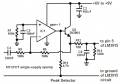
Feeding raw audio to the input of an LM3914 or LM3915 produces a blur of many instantaneous levels as said on the LM3915 datasheet. They recommend and show "peak detector circuits" to feed the pin 5 inputs with positive peak voltages stretched to about 30ms in duration so that you can clearly see the levels. Here is my peak detector circuit:
If the LM3914 REFOut pin is 1.25v, Q1 Pin will light at when input pin 5 is ~125mV.
What is connected to the CD4053B pins 3, 5, and 9? Can you post that part of the circuit?
BTW-
The schematic shows the LM3914 connected in BAR mode.
If the LM3914 REFOut pin is 1.25v, Q1 Pin will light at when input pin 5 is ~125mV.
What is connected to the CD4053B pins 3, 5, and 9? Can you post that part of the circuit?
BTW-
The schematic shows the LM3914 connected in BAR mode.
I still think pin 5 requires a DC path to ground for proper operation. I duplicated the circuit you posted and with pin5 not connected or floating I have the #10 LED always on. Connecting a 1meg resistor from pin5 to ground fixed that problem.
 Facebook
 Google
 GitHub
 Linkedin