LM3914 Flashing Circuit

Thread Starter

SpeedAddict62

Joined Jun 22, 2012
6
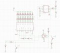
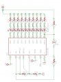
I'm having an issue with the flashing circuit on the LM3914. I'm using the alarm flasher circuit from the datasheet:http://www.ti.com/lit/ds/symlink/lm3914.pdf. It's designed for 5V, but I'm using it at 9V. It does work, kinda. It flashes at the high voltage reference, but above that it goes solid again. It also "latches," if the input voltage gets turned down, it keeps flashing until the voltage drops substantially. For reference, the low voltage is at 1.25V, the high is at 2.5V. Once it starts flashing, it doesn't stop until the input drops to 1.7V. I'm not entirely sure how the circuit works either. From what I can tell, C3 charges through R5. When LED10 turns on, that pin goes low and C3 discharges. After that, not really sure what is happening, other than it causes pin 6/7 on the 3914 to oscillate.

I want to remove the latch and get it to flash at any voltage above 2.5V, no matter what. Ideas? Datasheet says you can turn off the current sources by pulling positive on the reference pin with 100 uA or gating the input with a transistor.
 

Attachments

Dodgydave

Joined Jun 22, 2012
11,285
Try lowering the supply to 5v see what happens then, it may need the resistors altering, i don't think you need the series resistors in the leds,
 

Thread Starter

SpeedAddict62

Joined Jun 22, 2012
6
Right, I'll try that, and try changing out the resistors with something else. I can't run 5V all the time because I am drawing off a LM7809 that's powering other stuff too.

I am running the series resistors on the LEDs to reduce power dissipation on the 3914. Right now I'm drawing 20 mA (probably too much, it's really bright) from 9V so I'm using the resistors to drop the LED voltage down to 3V or so. I had 1 30 ohm 2W in there, but then the power dissipation isn't linear with the number of LEDs lit.
 

Dodgydave

Joined Jun 22, 2012
11,285
The resistor between pins 7 & 8 sets the led current, not the series resistors, so at the moment the 665R resistor is setting 1.8mA per led, thats 18mA total,
 

Thread Starter

SpeedAddict62

Joined Jun 22, 2012
6
The current out of pin 7 sets the current, and it's roughly 1/10 LED current. 1.25/665 = 1.89 mA, which means about 18.9 mA per LED. 18.9 mA*300 ohms is about 5.7V across the resistor to the LED, so the LED only sees 3.3V. The forward voltage is 2-3V depending on color, so the LM3914 never has to drop more than 1V at 18.9 mA, so maximum 18.9 mW per driver, and 189 mW with all LEDs on.
 

AnalogKid

Joined Aug 1, 2013
10,986
Unlike the circuit in the datasheet, you have Rlow (pin 4) connected to the feedback voltage from the last digit. It always is risky to "adapt" datasheet application example circuits. Frequently they work only when built exactly as shown.

ak
 

AnalogKid

Joined Aug 1, 2013
10,986
...and going to the + reference input is positive feedback to the comparators. This creates a hysteretic oscillator or a latch, depending on other circuit values and connections.

ak
 

Thread Starter

SpeedAddict62

Joined Jun 22, 2012
6
Thank you. I'm thinking about going about this a different way, like sensing when LED10 turns on, then using an oscillating circuit to drive a transistor that turns the input on and off quickly. It will appear to flash because the input will be pulled to ground and then go full scale when it turns back on. That way the flashing frequency is independent of the reference resistors, and I can change my voltage reference without worrying about the flashing circuit. Does that makes sense?
 

Thread Starter

SpeedAddict62

Joined Jun 22, 2012
6
Ok, here is what I've come up with. I'm sure there is a better way to do this, but this is what I know.

I've got a 555 timer set up as a 50% duty cycle astable oscillator to drive the flashing frequency at around 4 Hz. I've got a LM211 comparator hooked to the input to the LM3914 and the high voltage reference. When the input goes above the high voltage reference, the output of the LM211 floats, which makes the base of the transistor go high and pulls the input signal to ground. The 555 timer output is connected (not shown) to the 2nd transistor, the collector of which goes to the strobe pin. When current is pulled from the strobe pin, the output of the LM211 is shut off (if it's already floating, it may not do anything, I might have to switch that around).

Anyway, my questions are:
1. Why in the LMX111 datasheet does it show the strobe transistor with a resistor only on the emitter? Is that to provide negative feedback and act as a constant current draw? In that case, do I even need a base resistor?
2. Do I need a base resistor on the input gate transistor? It seems the pullup resistor is effectively limiting the current into the base.
3. Any other ways to do this that are potentially cleaner or with less component count?
 

Attachments

Top