I am aware of the 555. I have just built a emergency vehicle strobe quad light set up controlled by 1 x 555 and 1 x 556 so I have plenty of bits if required, what is your train of thought??
My thought is to use the LM3914 to enable the 555 timer. Then use the output of the timer to feed the two LM3914 ICs. I think you could feed the output of the 555 timer into the mode output to achieve a flash that would flash all but the most-significant LEDs in each array since the mode would be switching between the BAR and DOT display mode.
Does that sound like a reasonable scheme to you? Do you have any objection to having the top LED in each array stay on steady while the remaining LEDs flash at a rate governed by the 555 timer?
I was thinking of having the 555 flash on to off with a nearly 50% duty cycle.
I kinda need all the led's to flash, sorry for being akward. The circuit is for an LED rev counter for my 1982 classic mini which I am restoring. The flashing led's will act as a shift light
But I want 20 led's not ten, so I added another driver with the refLO of the 1st driver to 0V and the refHI of driver 1 to reflo of driver 2 & refhi of driver 2 to 8V. As you can see the last LED causes the led's to flash, but for me I need all twenty
I have a scheme that you may want to consider trying that involves the use of a 555 timer.
If it works as I anticipate, then it should result in all of the LEDs flashing on and off. There is an outside chance it will not work but I think it is simple enough that it is worth a try.
I am hoping to get it drawn up and posted in the next several hours.
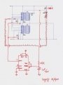
Here is the 555 timer schematic for what its worth.
Sorry for the poor resolution.
The idea behind it is that with the application of power to the circuit the 555 will quickly settle to the state that has the discharge (DISC) pin low and the trigger and threshold pins high. The 555 will stay in this stable state until the most significant LED is lit up. Once the top LED is lit, this will discharge the 555 timer's cap and thus the open-collector discharge signal will be tristated. I am hoping that the removal of the ground from the two 1.2K resistors will cause the LM3914 to turn off. If I am correct in this assumption then the LED arrays will turn off and the 555 timer's cap will charge back up through the combination of the 150K and the 47K resistor. Once the cap charges to 0.66Vcc (5.3V) then the discharge output will be driven low again. This starts the oscillation cycle all over again. I have calculated the flash frequency to be around 7.2 Hz.
Hi hgmjr,
Sorry for the delay in posting but the time difference here in the UK meant it was way past my bedtime when you posted the cct. Many thanks for the schematic. I built the cct in Livewire and although the circuit does work in theory there are issues, I can only get the leds to flash at FSD if ALL LEds are fed via the 100R, if the circuit is set up as designed with only the trigger LED fed via the 100R then the array does not flash at FSD,please see attached. Also what size cap is meant to be on pin 5 as the schematic has no value.
Of course it was not my intention to force the need to change the circuit in any way other than those changes I noted in my marked up schematic.
I'll do a bit more research to see if I can determine the reason the circuit fails to work unless all of the LEDs have a 100R in series with them.
The value of the capacitor on pin 5 is not critical. I believe the manufacturer recommends a 0.1 uFd.
In the meantime, it would be helpful if you could try connecting the 555 output from the discharge pin to circuit just one of the lm3914's. For this expriment make sure that you have the 100 ohm resistor connected to only the top LED. This experiment would validate (or not) whether the circuit would behave correctly in the single lm3914 case.
I suspect that the value of the 100 ohm resistor is too low.
What may be happening is that the voltage at the LM3914's pin 10 is not going close enough to ground to insure that the 555 timer is triggered so that output at pin 7 goes high which will set the 555 timer up to oscillate. I reasoned this from the fact that you needed to tie all of the LEDs to the positive supply rail through a common 100 ohm resistor. The result of this would be that the voltage level at the LM3914's pin 10 would be sure to go negative enough to trigger the 555 timer to switch the 555's internal discharge transistor connected to pin 7 of the 555.
If my reasoning is correct then the circuit should work properly if you connect it up as I originally suggested and then increase the value of the 100 ohm resistor to 200 or possibly 220 ohms. You may need to adjust this resistor value slightly up or down to achieve the proper brightness in the top LED while at the same time insuring that the 555 timer oscillates.
Sorry that this is taking so long to sort out. I don't have any of the needed component handy with which to try this hookup myself so we are working without a net so to speak.
Here is my stab at a schematic of what I have in mind. You will see that I have bumped the value of the 100 ohm resistor to 220 ohms in this version. If the top LED is is lit too dim then you will need to decrease this value to 200 ohms or perhaps 180 ohms. If the 555 timer does not oscillate then the value will need to be increased from 220 ohm to 240 ohm or perhaps 270.
hgmjr
PS: I just noticed that I accidently left off the connection of the mode pins for the two LM3914 IC's to the positive power supply. OOppppsss!!!
I don't know if you are still interested but I went ahead and breadboarded the design as I originally posted it earlier in this thread.
I found a couple of changes that optomized its performance. The changes were subtle but they resulted in worthwhile improvements.
I have attached the rev b version of the design for you. Two things in particular are worth noting. I increased R1 from 220 ohms to 470 ohms. This allowed the signal at the highest level LED driver pin of the LM3914 to swing closer to ground. This was needed to make sure that the 555 timer switched at a reasonable frequency.
You will also notice that I moved the two 1.2K resistors used to set the LED currents so that they are driven by the output of the 555 timer rather than its discharge pin. This takes advantage of the push/pull output from the 555 to crisply turn the LED bargraph off and on.
Here is a link to my googlepage where I have posted the AVI movie clip of the bargraph in operation. The filename of the clip is FlashingBargraph.avi. It is located at the bottom of the page.
The frequency of the flashing can be tailored to suit the application. This is just the rate I ended up with on my prototype.
Let know if you have any problems with your breadboard of the circuit.
 Facebook
 Google
 GitHub
 Linkedin