Not the last time I looked - unless you want to compare the input signal to 0V.
Its usual to provide one of the inputs with a Vref that can be obtained by various means. But I'm pretty sure I've seen examples of that input configuration in a few applications.
RMS voltage is not necessarily related to peak voltage by any specific factor for variable reluctance sensors. The waveform depends on the physical shape of the things being sensed. A fine toothed gear will produce an output that is reasonably sinusoidal. Something like a sprocket will produce a much different waveform which dwells at zero for some significant part of the cycle.
True, they don't care where the inputs are within the rail voltages under normal operating conditions.
But if they don't have a path for the input bias currents, then the inputs will go to one of the rails (depending upon the direction of the bias current) and the circuit will be saturated and not work.
If you don't believe give it a try with a real circuit.
True, they don't care where the inputs are within the rail voltages under normal operating conditions.
But if they don't have a path for the input bias currents, then the inputs will go to one of the rails (depending upon the direction of the bias current) and the circuit will be saturated and not work.
If you don't believe give it a try with a real circuit.
If your comparator is working correctly - the output is a square wave and the mean of the waveform is an entirely different equation.
A 50:50 square wave can be filtered to produce 1/2 Vcc - you can make PWM with 2 comparators, one generates a sawtooth, the other compares that sawtooth with the input level.
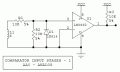
This is about as simple as the input can get. R2 prevents overdriving the input. The LM393 is a dual version of the 339. Just like it, its input common mode range extends below its negative rail, so GND can be use as a comparator trip point. The part has clamping diodes on the inputs, but National recommends an external diode to keep the input within 0.6 V of the rail, but some of National's app circuits do not show the diode. I show an external diode for completeness. If you change to an LM358/324, you no longer need R3.
Vee - 0.3 V (from memory). In practice, both the 393 and 358 have essentially identical PNP input stages, so it makes sense that things fall apart at Vee - 0.6 - ish. A common circuit to monitor a negative voltage with a positive-voltage-only monitoring system is to create a voltage divider from the positive reference voltage to the negative input, with 0 V as the trip point for the comparator. Been doing it for decades.
Vee - 0.3 V (from memory). In practice, both the 393 and 358 have essentially identical PNP input stages, so it makes sense that things fall apart at Vee - 0.6 - ish. A common circuit to monitor a negative voltage with a positive-voltage-only monitoring system is to create a voltage divider from the positive reference voltage to the negative input, with 0 V as the trip point for the comparator. Been doing it for decades.
Thinking more about the problem I had to solve, I think it was simply that I wanted to switch at 0V as you said. The switching was unreliable until I raised the other pin a few millivolts above ground.

 Facebook
 Google
 GitHub
 Linkedin