 Facebook
 Google
 GitHub
 Linkedin
Audioguru again
- Joined Oct 21, 2019
- 6,826
Maybe you bought a cheap Chinese copy of an LM338 from fleabay?
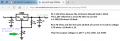
Here is how a real LM338 works:
Here is how a real LM338 works:
Attachments
-
 48.9 KB Views: 6
| Thread starter | Similar threads | Forum | Replies | Date |
|---|---|---|---|---|
| M | LM338T low output current | Power Electronics | 7 | |
| J | Help using an LM338T regulator | General Electronics Chat | 16 | |
| N | Voltage Regular Problem LM338T | General Electronics Chat | 1 | |
| 1 | Lm338T use and info | General Electronics Chat | 3 |


