LM338T

Thread Starter

PaulDFL

Joined Jan 1, 2020
49
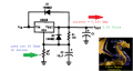
Setting the output to 6 volts with 12 volts input.
Using two 39 Ohms resistors in series.
This gives me 5.93 volts with 0.530 Amp load.
I encountered an unusual situation.
Needed to raise the voltage a bit, used two 150 Ohms in parallel, this dropped the output to 2 volts no load.
Tried again with a 47 ohms and a 27 Ohms in series...same output as above.
Can some one explain this to me?
 

dl324

Joined Mar 30, 2015
18,326
Welcome to AAC!

LM318 can't source or sink more than a couple dozen mA. It would be helpful if you posted a schematic.

EDIT: The original title referred to LM318 and was changed to LM338 by moderation.
 
Last edited:

Audioguru again

Joined Oct 21, 2019
6,826
R1 is almost always 120 ohms and has 1.25V across it. Then the current in R1 is 1.25V/120 ohms= 10.41mA. R2 has the same 10.41mA in it so if you want the output to be 6V then R2 must have 6V - 1.25V= 4.75V across it and its value must be 4.75V/10.41mA= 456.3 ohms.
The 1.25V might be a little higher or be a little lower. You can use 100 ohms for R1 if you recalculate its current and the different value for R2.
 

Thread Starter

PaulDFL

Joined Jan 1, 2020
49
R1 is almost always 120 ohms and has 1.25V across it. Then the current in R1 is 1.25V/120 ohms= 10.41mA. R2 has the same 10.41mA in it so if you want the output to be 6V then R2 must have 6V - 1.25V= 4.75V across it and its value must be 4.75V/10.41mA= 456.3 ohms.
The 1.25V might be a little higher or be a little lower. You can use 100 ohms for R1 if you recalculate its current and the different value for R2.
R1 is not the resistor in question.
It is R2. The resistor that varies the output voltage.
78 Ohms gives me the 5.93 volts with the 0.530 Amp load.
I needed to raise the voltage a bit.
Tried the combinations above, with the posted results.
The resistor combinations in theory, should have raised the voltage a small amount.
 

Thread Starter

PaulDFL

Joined Jan 1, 2020
49
R1 is almost always 120 ohms and has 1.25V across it. Then the current in R1 is 1.25V/120 ohms= 10.41mA. R2 has the same 10.41mA in it so if you want the output to be 6V then R2 must have 6V - 1.25V= 4.75V across it and its value must be 4.75V/10.41mA= 456.3 ohms.
The 1.25V might be a little higher or be a little lower. You can use 100 ohms for R1 if you recalculate its current and the different value for R2.
I compared my calculations with yours.
Found an error in the E/I for R2.
Have a stable 5.97 volts at 0.530 Amp.
R2 = 440 Ohms.
Thanks for the help.
 

crutschow

Joined Mar 14, 2008
38,503
For best regulation, the top of R1 should be connected directly to the LM338 output pin (not the circuit output terminal as you might expect).
That's because any resistance between that pin and the connection for R1 will significantly degrade the load regulation (due to the fact that the output pin is one of the internal voltage reference points).
And thus the connection from the LM338 output pin to the circuit output terminal should have low resistance.

Also the bottom of R2 should be connected directly to the output terminal common.
That minimizes the effect of the circuit ground resistance on regulation.

But normally the no load voltage is higher than the load voltage.
Did you mix up those two values?
 
Last edited:

Thread Starter

PaulDFL

Joined Jan 1, 2020
49
For best regulation, the top of R1 should be connected directly to the LM338 output pin (not the circuit output terminal as you might expect).
That's because any resistance between that pin and the connection for R1 will significantly degrade the load regulation (due to the fact that the output pin is one of the internal voltage reference points).
And thus the connection from the LM338 output pin to the circuit output terminal should have low resistance.

Also the bottom of R2 should be connected directly to the output terminal common.
That minimizes the effect of the circuit ground resistance on regulation.

But normally the no load voltage is higher than the load voltage.
Did you mix up those two values?
No. The 120 is in it's correct position as is R2. I'm happy it works as needed.
 

Thread Starter

PaulDFL

Joined Jan 1, 2020
49
The point we're trying to make is that it isn't working correctly.
The resistors are connected directly to the device terminals and in the proper places.
The voltage goes up to 5.97 from 5.72 when the load is applied.
 
Top