LM338K dropping voltage

Thread Starter

Paulo Matheus Vinhas

Joined Dec 15, 2018
5
I really have read a lot about the LM338, but still with problems.
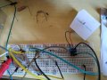
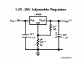
I'm making a regulator from 12DC to 5DC. The exactly attached circuit from data sheet.
R1 = 120ohms; R2 = 360Ohms. 5.23V Out.

I'm testing it with a small DC motor of 15mA but the out voltage drops to about 2.7V.
If I'm doing right the LM338K is dissipating (12-5.23)*15mA = 0.10155W, so I could ignore a heat sink.

What should I do to have the 5V on out?
 

Attachments

Ylli

Joined Nov 13, 2015
1,086
Be sure you have the pinout correct. And those capacitors need to be as close to the device as possible. Are you sure the motor only draws 15 mA? Seems low for a motor.
 

Reloadron

Joined Jan 15, 2015
7,501
Looking at this data sheet on page 12 doing the math, R1 = 270 Ohms and R2 = 820 Ohms for a 5.0 VDC out. What you have should work. Also, as mentioned placement of C1 & C2 is important as well as the pin out for your package. As long as your source Vin can provide the current I don't really see why it shouldn't work.

Ron.
 

crutschow

Joined Mar 14, 2008
34,283
Is the output 5V with no load?
If so, then either you have a wiring error or your motor is drawing a lot more than 15mA.
What is the 12V source?
 

Thread Starter

Paulo Matheus Vinhas

Joined Dec 15, 2018
5
Be sure you have the pinout correct. And those capacitors need to be as close to the device as possible. Are you sure the motor only draws 15 mA? Seems low for a motor.
Yes, the pinout are correct and the motor is a RF-300CA-09550, the third on the page below. It's a micro DC motor.
http://catalog.miniscience.com/catalog/motors/RF300CA.html

Looking at this data sheet on page 12 doing the math, R1 = 270 Ohms and R2 = 820 Ohms for a 5.0 VDC out. What you have should work. Also, as mentioned placement of C1 & C2 is important as well as the pin out for your package. As long as your source Vin can provide the current I don't really see why it shouldn't work.


Ron.
I did many tests with R1 and R2 and these values are good to me. Something about 5.23V.
My circuit is attached. I don't think it's a considerable distance. What do you think?
I'm using the MS-60-12, a 12V/5A switching power supply.

Is the output 5V with no load?
If so, then either you have a wiring error or your motor is drawing a lot more than 15mA.
What is the 12V source?
Yeah. 5V with no load.
I'm using the MS-60-12, a 12V/5A switching power supply.
I don't think my motor is drawing more current. I'm measuring it on real time.

Have you measured the input voltage WHEN THE OUTPUT IS LOADED ?

Les.
Yes, 12V on input with or without load.
 

Attachments

dl324

Joined Mar 30, 2015
16,845
Markings that come off easily are one of the signs of counterfeit parts...
upload_2018-12-16_10-51-31.png

A poor connection to the case could also cause problems.
 

Thread Starter

Paulo Matheus Vinhas

Joined Dec 15, 2018
5
Where did you get that "K" version of the 338?
Brazil.
Markings that come off easily are one of the signs of counterfeit parts...
View attachment 165925

A poor connection to the case could also cause problems.
Remade it with a screw and not resolve the problem. I'm wondering if it could not be the protoboard issue, but I read that protoboards usually hang around 100mA quietly and it's about 15mA.
IMG_20181216_172428.jpg

I'm going back to the store tomorrow to change the part. I did not take into consideration the markings coming off.
 

ebp

Joined Feb 8, 2018
2,332
It's too late now, but I would very strongly discourage plugging the pins of a TO-3 directly into a solderless breadboard. There is some variability, but they can be large enough to cause permanent spreading of the spring clips and, depending on the clip design, may make connections to other wires or parts plugged into the clip unreliable (i.e. plugged in at the same time as the TO-3).

If the output voltage is OK with no load, I would strongly suspect a poor connection either due to the breadboard or to a connecting wire. The stranded wires with the little pins are nice in many ways, but they are also subject to strands breaking near the pins and in consequence becoming high resistance.

When measuring voltages, always consider the "worst case place" to measure. For example, when measuring the input voltage, measure right on the pin of the regulator, not at the other end of a wire that is supposed to be connected to the pin - essentially the "destination" of the input voltage connections. The same applies for the connection point of the meter negative. "Ground" misconnections are often a source of difficulty. Check the voltage between the negative of the input power supply and the breadboard. If the voltage difference is very small, then move on to check other parts that should connect to ground right on their pins, not at adjacent points on the breadboard.

===
I just had a look at the TI datasheet for the part. Whoever make the package drawings on the first page is utterly clueless and whoever approved publication of that datasheet deserves demotion.
 

Thread Starter

Paulo Matheus Vinhas

Joined Dec 15, 2018
5
It's too late now, but I would very strongly discourage plugging the pins of a TO-3 directly into a solderless breadboard. There is some variability, but they can be large enough to cause permanent spreading of the spring clips and, depending on the clip design, may make connections to other wires or parts plugged into the clip unreliable (i.e. plugged in at the same time as the TO-3).

If the output voltage is OK with no load, I would strongly suspect a poor connection either due to the breadboard or to a connecting wire. The stranded wires with the little pins are nice in many ways, but they are also subject to strands breaking near the pins and in consequence becoming high resistance.

When measuring voltages, always consider the "worst case place" to measure. For example, when measuring the input voltage, measure right on the pin of the regulator, not at the other end of a wire that is supposed to be connected to the pin - essentially the "destination" of the input voltage connections. The same applies for the connection point of the meter negative. "Ground" misconnections are often a source of difficulty. Check the voltage between the negative of the input power supply and the breadboard. If the voltage difference is very small, then move on to check other parts that should connect to ground right on their pins, not at adjacent points on the breadboard.

===
I just had a look at the TI datasheet for the part. Whoever make the package drawings on the first page is utterly clueless and whoever approved publication of that datasheet deserves demotion.
That LM338K I'm using is from National Semiconductor. Attached data sheet.
TI bought national semiconductor on 2011, so It would be an old component. Anyway the output voltage is ok with no load so I do not think this is the problem. I changed the breadboard, and changed the wires but the problem persists.
I will try to change the component and test it right on a pcb with "wide" tracks, even believing that for 15mA the breadboard would serve. Remains your theory spreading of the spring clips. Let's check.
 

Attachments

ebp

Joined Feb 8, 2018
2,332
At the current you require, the breadboard itself, if the connections are good, should be perfectly OK. Even at 10 time that current I wouldn't expect a big error.

It would be unusual for the regulator to provide the required voltage at no load and change so much with a light load, but it isn't totally impossible.

There is a slight chance the circuit is oscillating. To try to evaluate this with just a meter, try this:

Put your meter on AC volts and measure any DC source that you know is quite stable - any battery, for example. If the meter reads zero or very close (it may take a few seconds to stabilize), then you can proceed - the meter has an internal DC blocking capacitor (some do, some don't). If the meter displays anything more than a few millivolts with a battery, perhaps a little more with a power supply (your switch mode supply might give a moderately high reading because of noise), then you will need to use an external DC blocking capacitor. With a typical meter with 10 megohms input resistance, and ceramic or plastic film capacitor in the range of 0.1 to 1 microfarad would be fine. Electrolytic capacitors aren't suitable because the normal DC leakage current could allow a reading of several volts. Double check with the capacitor in place to be sure the meter reading is very low with a good DC source.

With the motor connected and the DC output voltage low, measure the output with the meter arranged as above. If the regulator output voltage is low but stable, you would again expect to read only a few millivolts on the AC scale. If you read hundreds of millivolts or even volts, it is a clear sign that the circuit is oscillating.

Oscillation is a sign that you need good capacitors very close to both the input and output of the regulator. Use the shortest possible leads and the most direct path. Don't use connecting wires between the regulator and the capacitor unless you absolutely have to, and then use short pieces, not the long wires as shown in your photo. Usually these ICs don't oscillate even without the capacitors, they just don't regulate accurately if the load current changes quickly. But sometimes you do get strange behavior that the capacitors will fix.

==
I wouldn't be too concerned with the markings rubbing off. It can be an indication the part is a counterfeit, but I have seen it happen on genuine parts.
 

Thread Starter

Paulo Matheus Vinhas

Joined Dec 15, 2018
5
At the current you require, the breadboard itself, if the connections are good, should be perfectly OK. Even at 10 time that current I wouldn't expect a big error.

It would be unusual for the regulator to provide the required voltage at no load and change so much with a light load, but it isn't totally impossible.

There is a slight chance the circuit is oscillating. To try to evaluate this with just a meter, try this:

Put your meter on AC volts and measure any DC source that you know is quite stable - any battery, for example. If the meter reads zero or very close (it may take a few seconds to stabilize), then you can proceed - the meter has an internal DC blocking capacitor (some do, some don't). If the meter displays anything more than a few millivolts with a battery, perhaps a little more with a power supply (your switch mode supply might give a moderately high reading because of noise), then you will need to use an external DC blocking capacitor. With a typical meter with 10 megohms input resistance, and ceramic or plastic film capacitor in the range of 0.1 to 1 microfarad would be fine. Electrolytic capacitors aren't suitable because the normal DC leakage current could allow a reading of several volts. Double check with the capacitor in place to be sure the meter reading is very low with a good DC source.

With the motor connected and the DC output voltage low, measure the output with the meter arranged as above. If the regulator output voltage is low but stable, you would again expect to read only a few millivolts on the AC scale. If you read hundreds of millivolts or even volts, it is a clear sign that the circuit is oscillating.

Oscillation is a sign that you need good capacitors very close to both the input and output of the regulator. Use the shortest possible leads and the most direct path. Don't use connecting wires between the regulator and the capacitor unless you absolutely have to, and then use short pieces, not the long wires as shown in your photo. Usually these ICs don't oscillate even without the capacitors, they just don't regulate accurately if the load current changes quickly. But sometimes you do get strange behavior that the capacitors will fix.

==
I wouldn't be too concerned with the markings rubbing off. It can be an indication the part is a counterfeit, but I have seen it happen on genuine parts.
Tried to put my meter on AC volts and measure a battery but it reads too much high, about Volts, so I consider that I need to use an external DC blocking capacitor. Right? But I'm not with much time this week, and can't go to store to buy these value of resistor and capacitor that I don't have so I consider that my circuit is oscillating and now I'm doing a PCB test.
What do you think about these distances and lines width? (attach)

EDIT: have an error on R1 second line. Already saw.
 

Attachments

Last edited:
Top