 Facebook
 Google
 GitHub
 Linkedin
Hello,
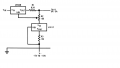
I have use this schematic to adjust voltage and it work very well. But now i want to adjust also the current. What can i add to this schematic to make it available.
Thank you.
I have use this schematic to adjust voltage and it work very well. But now i want to adjust also the current. What can i add to this schematic to make it available.
Thank you.
Attachments
-
 55.2 KB Views: 41


")


