I suggest that you do not measure the current directly.
Instead, use a 1 Ohm 10 Watt resistor from the output to ground for a load.
Measure the voltage across the resistor. Since I=E/R, the voltage across the resistor will be equal to the current in Amperes through the resistor. 1 Volt across 1 Ohms = 1 Amperes
I am going to make one more try to break the circuit down a bit more so that you understand it.
I am only going to post the first two parts now. See if you understand them.
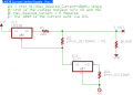
in this diagram
if i desired current = 500mA
then R2= 2.26Ω (VRef U1/Current-R1) using you type this formual
i am ok or not
i am desired for current limiting using this digital cct
use fix resistance
My problem is not solved
because i am trying to make digital current limiting cct
Attatch image
if Q1 is on than output current = ?
if Q2 is on than output current = ?
if both in parallal than output current = ?
this cct is ok or not
R2 and R3 wattage 1/2 W
using counter change the resister
Resistor use in 1,2,4,8,16 step current 100,200,400,800,1600mA step
Please help me
2. Why output not short. i am seen any current regulator supply, current variable vary the output current if the output short and current meter across it for display max output current regulate
I have had to quote/edit your post as the image was not displaying.
Now I can see the image. That one is obsolete, as I made a couple of errors in it.
This is the corrected version you should refer to now:
in this diagram
if i desired current = 500mA
then R2= 2.26Ω (VRef U1/Current)-R1 using you type this formula [I have corrected your formula]
i am ok or not
i am desired for current limiting using this digital cct
use fix resistance
My problem is not solved
because i am trying to make digital current limiting cct
Attatch image
if Q1 is on than output current = ?
if Q2 is on than output current = ?
if both in parallal than output current = ?
this cct is ok or not
R2 and R3 wattage 1/2 W
using counter change the resister
Resistor use in 1,2,4,8,16 step current 100,200,400,800,1600mA step
Please help me
2. Why output not short. i am seen any current regulator supply, current variable vary the output current if the output short and current meter across it for display max output current regulate
The Part 1 schematic shows the most basic schematic from the datasheet for a current limiter.
The Part 2 schematic builds on the basic schematic. If the Vrefs are properly measured and formulas are followed to select the resistances, the Part 2 schematic should have an output current of exactly 0 (zero) Amperes.
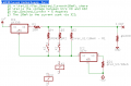
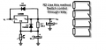
Now, here is Part 3:
Note the addition of R3, R4, and the two relays.
R3 is the same value as R2. If K1 is closed, then R3 and R2 are in parallel. Output from the regulator should then be 2.5 Amperes.
R4 is twice the value of R2. If K2 alone is closed, then R4 and R2 are in parallel, and current output from the regulator is 1.25 Amperes.
If both K1 and K2 are closed, then the three resistors are in parallel, and the output from the regulator is 3.75 Amperes.
In this way, you can add more resistors/relay contacts like R4/K2, each resistor being twice the value of the previous resistor.
The relays should be reed-type, which require very little current to switch, and have very low contact resistance. This is the only method that I can suggest to control the selection of resistors, as semiconductors would interfere with the resistor values, and would not provide isolation.
Let's say that you measured U1's Vref to be exactly 1.2525 Volts.
You want the maximum output current to be 5A.
You have to add in the 10mA sink current from the LM317 circuit.
So, R1 = Vref_U1/(5A+10mA) = 1.2525/5.01 = 0.25 Ohms.
R3 is easy. R3 = R2 = 125 Ohms. This provides 2.5A output.
R4 = R3*2 = 250 Ohms. This provides 1.25A output.
If you add an R5, it would be R4 * 2 = 500 Ohms. This provides 625mA output.
If you add an R6, it would be R5 * 2 = 1000 Ohms. This provides 312.5mA output.
Keep adding resistor/relay combinations, until you get the resolution that you require.
R3 is easy. R3 = R2 = 125 Ohms. This provides 2.5A output.
R4 = R3*2 = 250 Ohms. This provides 1.25A output.
If you add an R5, it would be R4 * 2 = 500 Ohms. This provides 625mA output.
If you add an R6, it would be R5 * 2 = 1000 Ohms. This provides 312.5mA output.
Quote:
R3 is easy. R3 = R2 = 125 Ohms. This provides 2.5A output.
R4 = R3*2 = 250 Ohms. This provides 1.25A output.
If you add an R5, it would be R4 * 2 = 500 Ohms. This provides 625mA output.
If you add an R6, it would be R5 * 2 = 1000 Ohms. This provides 312.5mA output.
In the data sheet the variable resister value = 150Ω that output current vary the 0-5A
In the datasheet, they used a 150 Ohm pot (potentiometer) for R2.
But since you want digital control, you cannot really use a potentiometer.
So in the new circuit, there is one resistor, R2, that establishes the zero output current point. The current coming out of the regulators OUT terminal matches the current flowing through resistor R2, so there is no output current.
Adding resistors in parallel with R2 increases the current flow necessary through R1 in order to maintain Vref.
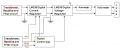
I do not see the LM317 current sink in your block diagram. If they are in the digital control circuit portion, then it is OK.
I don't know why you have -ve going directly to the 1st LM338.
Note that you have to account for the extra current that the 2nd LM338 will require for its voltage control circuit, otherwise your current limiter will be too low by that amount of current. You need to show how you are planning to control the 2nd LM338.
2. if the out put load short than max 5A current and no any damage (this state is true or false)
The second block (LM338 Digital current regulator) use this cct -Ve supply use this cct
Note that you have to account for the extra current that the 2nd LM338 will require for its voltage control circuit, otherwise your current limiter will be too low by that amount of current. You need to show how you are planning to control the 2nd LM338.
Digital voltage regulator cct Attatch
How many current use for this block (LM338 Digital voltage regulator)
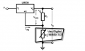
Resistor R2 use Fix Resistor(In series no of Bits 1,2,4,8,16,32) Bits control through relay cct (Open or short resistor)
You need to first determine the Vref of this LM338.
1) Connect a 100 Ohm resistor from OUT to ADJ.
2) Ground the ADJ terminal.
3) Connect 4v to 9v to the IN terminal.
4) Measure the voltage from OUT to ADJ.
5) Calculate: R1 = Vref/10mA
This additional 10mA current will have to be added to the current limiter's output current calculation.
So, instead of:
R1 = Vref_U1/(Max_Desired_Current+10mA)
the formula changes to:
R1 = Vref_U1/(Max_Desired_Current+20mA)
Resistor R2 use Fix Resistor(In series no of Bits 1,2,4,8,16,32) Bits control through relay cct (Open or short resistor)
If the low side of R2 is connected to ground, you will not be able to output a regulated voltage less than Vref, even if R2=0 Ohms. Vref will be between 1.2v and 1.3v, inclusive.
It depends upon what voltage you are using for the input supply.
Let us say, for example, that you are going to use 30v for the unregulated supply input.
If the output of the current limiting regulator is shorted to ground with 5A output selected, that means the power dissipation in the regulator will be:
P = (30v-Vref) * Iout
P = (30v-1.25v)*5.01A [assuming Vref=1.25v]
P = 28.75v * 5.01A
P = 144 Watts.
You will need a heat sink large enough to dissipate 144 Watts, or the LM338 will go into thermal shutdown. This will be a large heat sink made from copper with a big fan blowing cool air on it.
If the low side of R2 is connected to ground, you will not be able to output a regulated voltage less than Vref, even if R2=0 Ohms. Vref will be between 1.2v and 1.3v, inclusive.
You will need a heat sink large enough to dissipate 144 Watts, or the LM338 will go into thermal shutdown. This will be a large heat sink made from copper with a big fan blowing cool air on it.
Copper is almost twice as efficient at conducting heat than aluminum is.
If you don't mind your power supply shutting down on you, and having to replace the LM338 regulator every few days, go ahead and use a small aluminum heat sink.
If you do not want the power supply to shut down on you, or have to replace the LM338 regulator every few days, then use a large copper heat sink cooled by a powerful fan.
 Facebook
 Google
 GitHub
 Linkedin