 Facebook
 Google
 GitHub
 Linkedin
Hi,
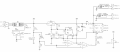
A battery charging circuit below is supposed to give out max charging voltage of around 14.5V and trickle charge voltage of around 13.5V. These values are supposed to be controlled by VR1 and VR9 respectively. However, in real life I'm only able to increase the voltage up to around 10 volts.
I have wired LM317T separately according to the datasheet to verify the that such resistor values would give me the desired output and they did.
I have built the circuit without the 7805, TSR2450,TSR2433 regulators on a breadboard It worked like a charm in the sense that i could control the output voltages with the pots. Then i made both a PCB and stripboard design with full circuit displayed in the image below and in both of them the output can be controlled as far as around 10 V leading me to believe that maybe the regulators introduced some problem but I'm not smart enough to figure it out after many hours of troubleshooting.
Any help would be greatly appreciated")
*The circuit design was based on a design suggested by forum user with the username crutschow. A link is included for reference to his original design and explantion https://www.electro-tech-online.com...ith-3-step-auto-cc-cv-and-trickle-charge.865/
A battery charging circuit below is supposed to give out max charging voltage of around 14.5V and trickle charge voltage of around 13.5V. These values are supposed to be controlled by VR1 and VR9 respectively. However, in real life I'm only able to increase the voltage up to around 10 volts.
I have wired LM317T separately according to the datasheet to verify the that such resistor values would give me the desired output and they did.
I have built the circuit without the 7805, TSR2450,TSR2433 regulators on a breadboard It worked like a charm in the sense that i could control the output voltages with the pots. Then i made both a PCB and stripboard design with full circuit displayed in the image below and in both of them the output can be controlled as far as around 10 V leading me to believe that maybe the regulators introduced some problem but I'm not smart enough to figure it out after many hours of troubleshooting.
Any help would be greatly appreciated
*The circuit design was based on a design suggested by forum user with the username crutschow. A link is included for reference to his original design and explantion https://www.electro-tech-online.com...ith-3-step-auto-cc-cv-and-trickle-charge.865/
Attachments
-
 171.6 KB Views: 54


