Facebook
 Google
 GitHub
 Linkedin
I've got a bunch of these and they all behave in the same way, so I'm doing something wrong.
I'm using the output calc and schematic here: https://circuitdigest.com/calculators/lm317-resistor-voltage-calculator
I'm trying to get it to near it's minimum so for R1 and R2 I'm using the same value.
However:
The output is always about .7v-1v lower than the input. So at 9v on the in pin I get 8.3v on the output.
I've used 110, 220, and 1000 ohm for resistors (r1=r2). Doesn't seem to make a difference.
Tried with and without capacitors in the datasheet: https://www.onsemi.com/pub/Collateral/LM317T-D.PDF
Switched out all the components, boards, and power supplies multiple times.
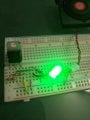
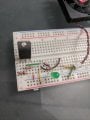
Attached image of one of my attempts. r1 = r2=220 ohm
A small van and an led with 1000ohm resistor on the output to make sure it has some load.
input pin is set to 9v and the output I'm getting is 8.3v.
What have I goofed?
I'm using the output calc and schematic here: https://circuitdigest.com/calculators/lm317-resistor-voltage-calculator
I'm trying to get it to near it's minimum so for R1 and R2 I'm using the same value.
However:
The output is always about .7v-1v lower than the input. So at 9v on the in pin I get 8.3v on the output.
I've used 110, 220, and 1000 ohm for resistors (r1=r2). Doesn't seem to make a difference.
Tried with and without capacitors in the datasheet: https://www.onsemi.com/pub/Collateral/LM317T-D.PDF
Switched out all the components, boards, and power supplies multiple times.
Attached image of one of my attempts. r1 = r2=220 ohm
A small van and an led with 1000ohm resistor on the output to make sure it has some load.
input pin is set to 9v and the output I'm getting is 8.3v.
What have I goofed?
Attachments
-
 4.3 MB Views: 21