LM317T battery charger circuit questions

#12

Joined Nov 30, 2010
18,224
datasheets and they say that the Collector current is 15A continuous.
Just a bit of general information:
When you start looking at maximums, you must keep in mind that maximums always interact with other limitations. This is why the comments about heat. You can only do 15 amps if you keep it cool. You can only use a 2N3055 at 70 volts if the current stays below the wattage rating. This is why you never see a transistor used in a way that maximum voltage and current are happening at the same time.
 

AlbertHall

Joined Jun 4, 2014
12,640
Just a bit of general information:
When you start looking at maximums, you must keep in mind that maximums always interact with other limitations. This is why the comments about heat. You can only do 15 amps if you keep it cool. You can only use a 2N3055 at 70 volts if the current stays below the wattage rating. This is why you never see a transistor used in a way that maximum voltage and current are happening at the same time.
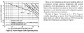
Not to mention safe operating area:
upload_2016-11-18_1-21-54.png
 

#12

Joined Nov 30, 2010
18,224
I see by the (post #22) graph that one 2N3055 has a limit at 60 volts.
I promise that I remember some brand of 3055 with a 70 volt limit.
Here's one claiming 100 volts.
I thought this was not an option when using standard numbering systems (JDEC?).:confused:
 

Attachments

Thread Starter

Max12345

Joined Aug 27, 2013
63
The problem is not so much the maximum current, but the maximum power in the transistor. For a regulator there is usually a fair amount of voltage across the transistor. Let's say 4 volts so if the current is 10 amps that's 40 watts in the transistor. Well you might say the 3055 is good for 115 watts and it is. But only if you can keep the case at 25C. So even at 40 watts the heat sink gets quite large. I should have ask you how big the heat sink is. Or sometimes they mount them on the case and use that.
I think the first circuit may be ok. The second is not so good. It will work, but the regulators won't share equally. Either way you somehow have to get rid of the heat.
Maybe we can "guesstimate" your transformer. Any idea how much it weighs or how big it is? Is there a fan?
3C per watt.
I guess you could just build it and measure how hot it gets.

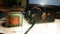
The transformer weighs only 1.25Kg. There is no fan. The dimensions are indicated on the attached pic.
It does seem rather "lightweight" doesn't it?

I have a transformer which I am using in a power supply which is a fair bit larger and heavier and IT is rated at 7A only.

So this one probably is a 5A transformer. Good call ronv!

Guess I'll stick with the 5A LM388 for now until I acquire a more robust transformer.

I'll post a circuit later for comments if I may...
 

Attachments

Johann

Joined Nov 27, 2006
190
The transformer weighs only 1.25Kg. There is no fan. The dimensions are indicated on the attached pic.
It does seem rather "lightweight" doesn't it?

I have a transformer which I am using in a power supply which is a fair bit larger and heavier and IT is rated at 7A only.

So this one probably is a 5A transformer. Good call ronv!

Guess I'll stick with the 5A LM388 for now until I acquire a more robust transformer.

I'll post a circuit later for comments if I may...
From the dimensions of the transformer, I "guestimate" it to be nothing bigger than 100VA. From this you can determine its max current after measuring the open circuit secondary voltage. (I = P/V) . A safe DC max current would be 80% of this value. Hereafter you may plan the rest of your circuit.
 

Johann

Joined Nov 27, 2006
190
It should be kept in mind that the actual current is caused by the difference between the DCV out from the charger and the DCV of the battery and this is what limits the current the current in an unregulated design.
 

Johann

Joined Nov 27, 2006
190
In an unregulated (Transformer, bridge rectifier and ammeter only) design, a good ball-park figure for the secondary rms voltage on a 100 VA transformer, is 13 V rms.
 

ronv

Joined Nov 12, 2008
3,770
The transformer weighs only 1.25Kg. There is no fan. The dimensions are indicated on the attached pic.
It does seem rather "lightweight" doesn't it?

I have a transformer which I am using in a power supply which is a fair bit larger and heavier and IT is rated at 7A only.

So this one probably is a 5A transformer. Good call ronv!

Guess I'll stick with the 5A LM388 for now until I acquire a more robust transformer.

I'll post a circuit later for comments if I may...
The weight would put it at about 3 amps. But only based on a rule of thumb of 20 watts per pound.
 

Thread Starter

Max12345

Joined Aug 27, 2013
63
Not to mention safe operating area:
View attachment 115471
AlbertHall,thanks for the graph. I'm learning all the time.

Looks pretty good.
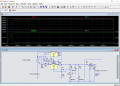
ronv, thanks for the trouble you took to do a LTSpice simulation of the parallel LM350s. I see they are rated at 3A.

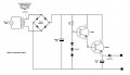
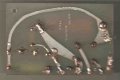
AlbertHall and Johann, I made sketches before I removed the original PCB and a pic of the dismantled PCB and I am attaching the original (re-engineered) circuit. It was not complex but I hope I got it right. Adding this more for interest. I also noticed that the board says "PSU 6". Power supply unit?


Max
 

Attachments

Johann

Joined Nov 27, 2006
190
Yes, PSU would stand for power supply unit. The direction of the "Zeners" seems to be reversed, unless they are diodes causing a voltage reference of 3 x 0.6V?
 

Johann

Joined Nov 27, 2006
190
AlbertHall,thanks for the graph. I'm learning all the time.


ronv, thanks for the trouble you took to do a LTSpice simulation of the parallel LM350s. I see they are rated at 3A.

AlbertHall and Johann, I made sketches before I removed the original PCB and a pic of the dismantled PCB and I am attaching the original (re-engineered) circuit. It was not complex but I hope I got it right. Adding this more for interest. I also noticed that the board says "PSU 6". Power supply unit?


Max
Yes, Darlington configuration with voltage reference (diodes or Zeners) on the base. Classical emitter follower circuit. Low output impedance. Vout = Vbase -(0.6 V + 0.6 V). Big diode prevents feed-back from the battery on charge.
 

Thread Starter

Max12345

Joined Aug 27, 2013
63
Yes, the zener diodes are drawn in backwards. Can you read a part number on them?

ak
AnalogKid, the diodes looked like typical Zeners but almost all the markings had disappeared. They were quite small. Thanks for confirming the reversed Zeners. Can you guess as to their voltage and power?
Yes, Darlington configuration with voltage reference (diodes or Zeners) on the base. Classical emitter follower circuit. Low output impedance. Vout = Vbase -(0.6 V + 0.6 V). Big diode prevents feed-back from the battery on charge.
Johann, thanks for pointing out the reversed Zeners. Any idea as to voltage and power of the Zeners?
 
I too used to use the LM317's but now use DC-DC converters. They run more efficiently and a lot cooler.
I understand the feeling when building your own charger but using theses gives a better feeling!

If you supply the DC-DC converter 16v or more, you will output more current to the battery than the input current from the transformer.

I use these converters which has both current limiting and voltage adjustment.... http://www.ebay.co.uk/itm/LM2596-DC...211511?hash=item4620c0b777:g:OVQAAOSwPc9W1P~r

I would use a blocking diode on the output to stop and voltage feedback/draining when ever the supply power is disconnected.
 
Top